Horizontal effective ground stress testing method and device

A stress testing and effective technology, applied in earth-moving drilling, wellbore/well components, etc., can solve the problems of inaccurate principal stress direction, low test success rate, and increased test cost, which is easy to implement and conducive to popularization. Application, low cost effect

Active Publication Date: 2018-10-23
SICHUAN UNIV
View PDF13 Cites 5 Cited by
  • Summary
  • Abstract
  • Description
  • Claims
  • Application Information

AI Technical Summary

Problems solved by technology

However, the above-mentioned in-situ stress testing methods all have different limitations. For example, the hydraulic fracturing method has the inaccurate direction of the principal stress, and the interpretation of the injection pressure curve, especially the constant pressure, is sometimes very difficult.
Hollow inclusion stress relief method and casing stress relief method also have certain requirements on geological conditions and cored rocks, and further processing of the drilled borehole is required, and strain gauges are pasted in the borehole. The release method also has problems such as small holes being out of axis, and a complete core is required to pull out the core during the process of setting the core. Not only is the operation complicated, but the above problems will easily lead to a low test success rate and increase the test cost.

Method used


Image

  • Horizontal effective ground stress testing method and device
  • Horizontal effective ground stress testing method and device
  • Horizontal effective ground stress testing method and device

Examples


Embodiment 1

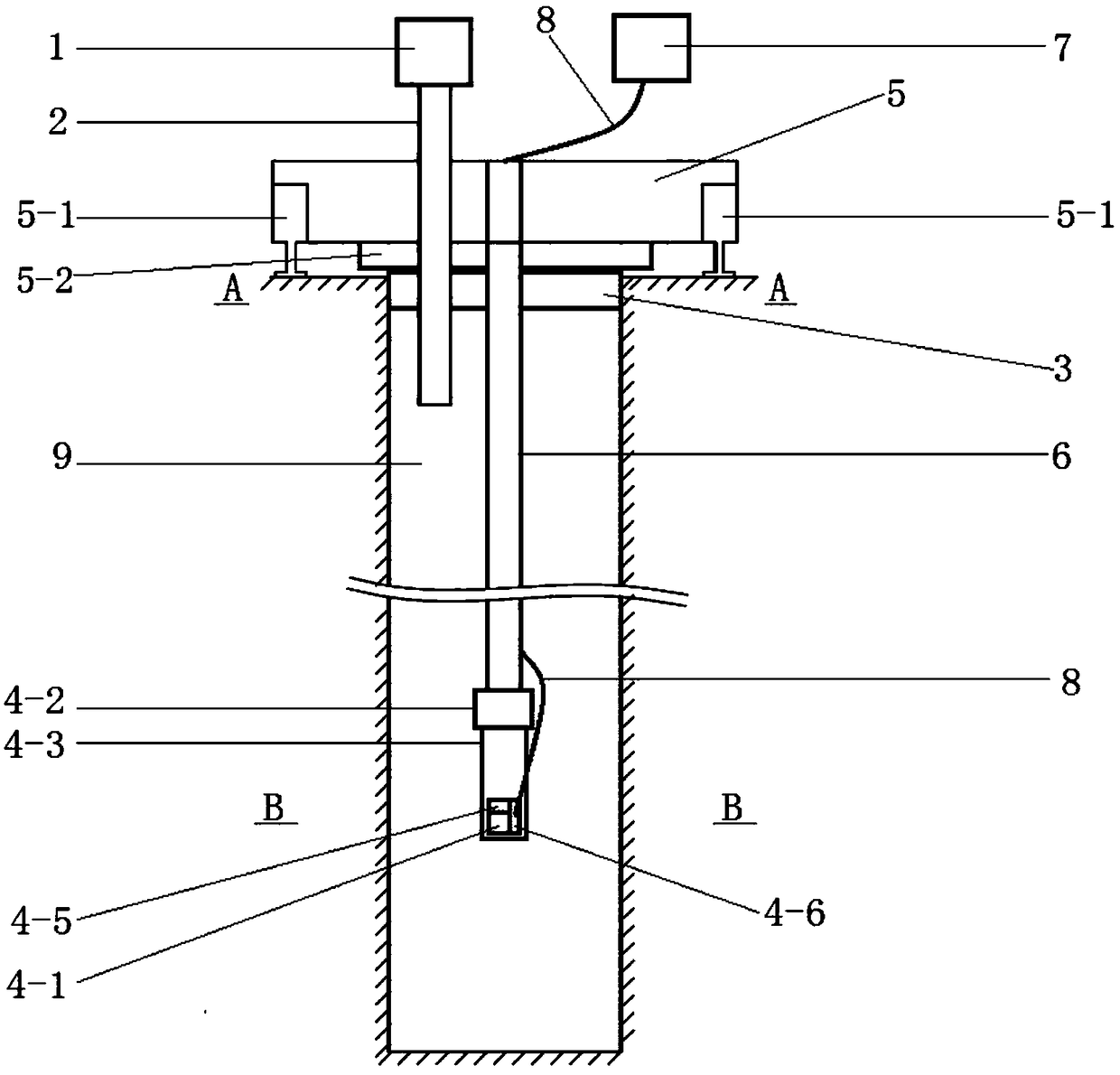
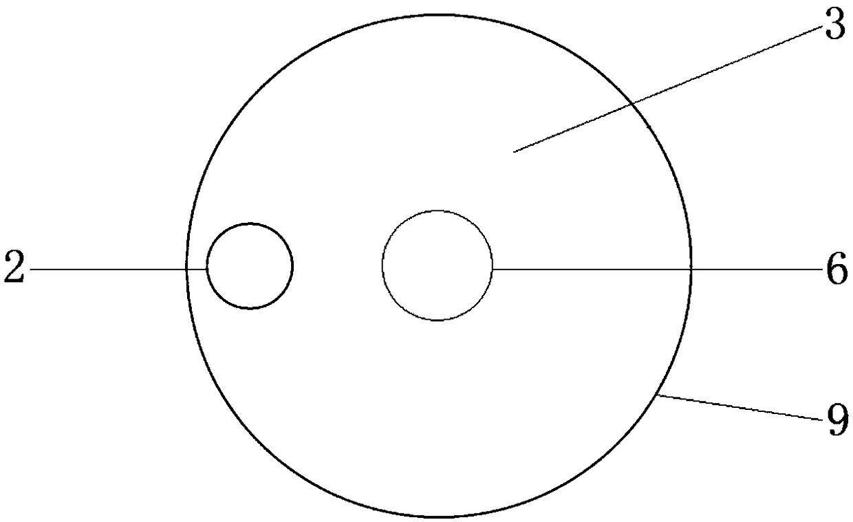
[0035] In this embodiment, a horizontally effective stress testing device is provided, and the structural diagram of the device is as follows Figure 1~3 As shown, it includes a grouting device 1, a grouting pipe 2, a borehole seal 3, a borehole shape and pressure measurement system, a support fixture 5, a connecting rod 6 and a computer processing system 7, and the borehole seal 3 has a thickness of 150 mm. 1. A rubber seal whose diameter matches the inner diameter of the borehole, and a round hole whose diameter matches the outer diameter of the grouting pipe and the connecting rod. The connecting rod is formed by threading a plurality of hollow drill pipes.

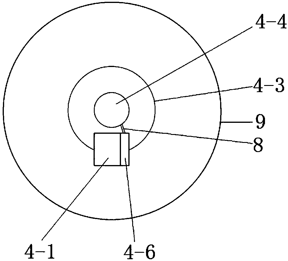
[0036] The drilling shape and pressure measurement system includes a multi-scale phase laser rangefinder 4-1, a motor 4-2, a detection axis 4-3, a three-dimensional electronic compass 4-4, a pressure sensor 4-5 and a data integration chip 4-6 , the motor 4-2 is powered by two sets of rechargeable Ni-MH batteries with r...

Embodiment 2

[0040] In this embodiment, a horizontally effective stress test method is provided, which uses the horizontally effective stress test device in Example 1 for testing, and the process schematic diagram of the method is as follows Figure 4 As shown, the steps are as follows:

[0041] ① Drill a hole perpendicular to the horizontal plane on the target rock mass, place the support bracket above the drill hole, adjust the height of the support feet so that the support bracket is in a horizontal state, connect the drilling shape and the motor of the pressure measurement system to the Rod connection, adjust the length of the connecting rod, send the connecting rod installed with the drilling shape and pressure measurement system into the borehole so that the drilling shape and pressure measurement system are immersed in the drilling fluid remaining in the drilling hole when drilling the hole, When the drilling shape and the pressure measurement system reach the target depth, fix the ...


PUM


Abstract

The invention provides a horizontal effective ground stress testing method. The method is established on the basis of a formula of a plane circular hole displacement elastic solution and a thick-wallcylinder, and the principle of the method is that in-situ ground stress is deduced reversely by restoring hole edge displacement deformation under the action of ground stress. The invention further provides a horizontal effective ground stress testing device. The device comprises a grouting device, a grouting pipe, a drilling sealing element, a drilled hole form and pressure measuring system, a supporting fixing frame, a connecting rod and a computer processing system. The drilled hole form and pressure measuring system comprises a multi-optical-scale phase laser range finder, a motor, a detection shaft, a three-dimensional electronic compass, a pressure sensor and a data integration chip. The computer processing system is connected with the data integration chip through a data line; a drilled hole is perpendicular to the horizontal plane, the grouting pipe is used for making the grouting device communicated with the drilled hole, the drilling form and the pressure measuring system isfixed to the supporting fixing frame through the connecting rod, the axis of the detection shaft coincides with the axis of the drilled hole, and a drilling opening is sealed through the drilling sealing element.

Description

technical field [0001] The invention belongs to the field of geostress testing, and relates to a horizontally effective stress testing method and a testing device. Background technique [0002] In-situ stress is the natural stress that exists in the formation without engineering disturbance, also known as rock mass initial stress, absolute stress or original rock stress. The state of in-situ stress is of great significance for earthquake prediction, evaluation of regional crustal stability, research on rockbursts in high in-situ stress areas, and coal and gas outbursts. According to the different test methods, the ground stress test methods can be divided into structural method, deformation method, electromagnetic method, seismic method and radiation method. According to different measurement principles, in-situ stress testing methods can be divided into stress recovery method, stress relief method, strain recovery method, strain relief method, hydraulic fracturing method, ...

Claims


Application Information

Patent Timeline
Patent Type & Authority Applications(China)
IPC IPC(8): E21B49/00
CPCE21B49/005
Inventor 高明忠陆彤吕有厂张建国汪文勇刘强陈海亮彭高友王明耀王飞
Owner SICHUAN UNIV
Why Eureka
Try Eureka