
Water tank self-cleaning and disinfection device for environmental protection water treatment

A disinfection device and environmentally friendly water technology, which is applied in water/sewage treatment, water/sludge/sewage treatment, sterilization/microdynamic water/sewage treatment, etc., can solve the problems of water quality without impurities, rust in water tanks, Unsatisfactory disinfection and other problems, to increase the effect of disinfection treatment and improve the effect of contact

Inactive Publication Date: 2018-10-26
程度
View PDF6 Cites 0 Cited by
  • Summary
  • Abstract
  • Description
  • Claims
  • Application Information

AI Technical Summary

Problems solved by technology

[0007] In order to solve the above-mentioned technical problems, the present invention provides a water tank self-cleaning and disinfecting device for environmental protection water treatment, to solve the problem that in the traditional water tank sterilizer proposed in the above-mentioned background technology, the water source used is not all high-quality water source. Before the water enters the water tank, there is no guarantee that there will be no impurities in the water quality, which will easily cause water rust inside the water tank. Secondly, when the water is disinfected by the disinfectant gas, the contact effect between the disinfectant gas and the water is poor, and the disinfection is not ideal.

Method used


Image

  • Water tank self-cleaning and disinfection device for environmental protection water treatment
  • Water tank self-cleaning and disinfection device for environmental protection water treatment
  • Water tank self-cleaning and disinfection device for environmental protection water treatment

Examples


Embodiment

[0034] as attached figure 1 to the attached Figure 8 shown:

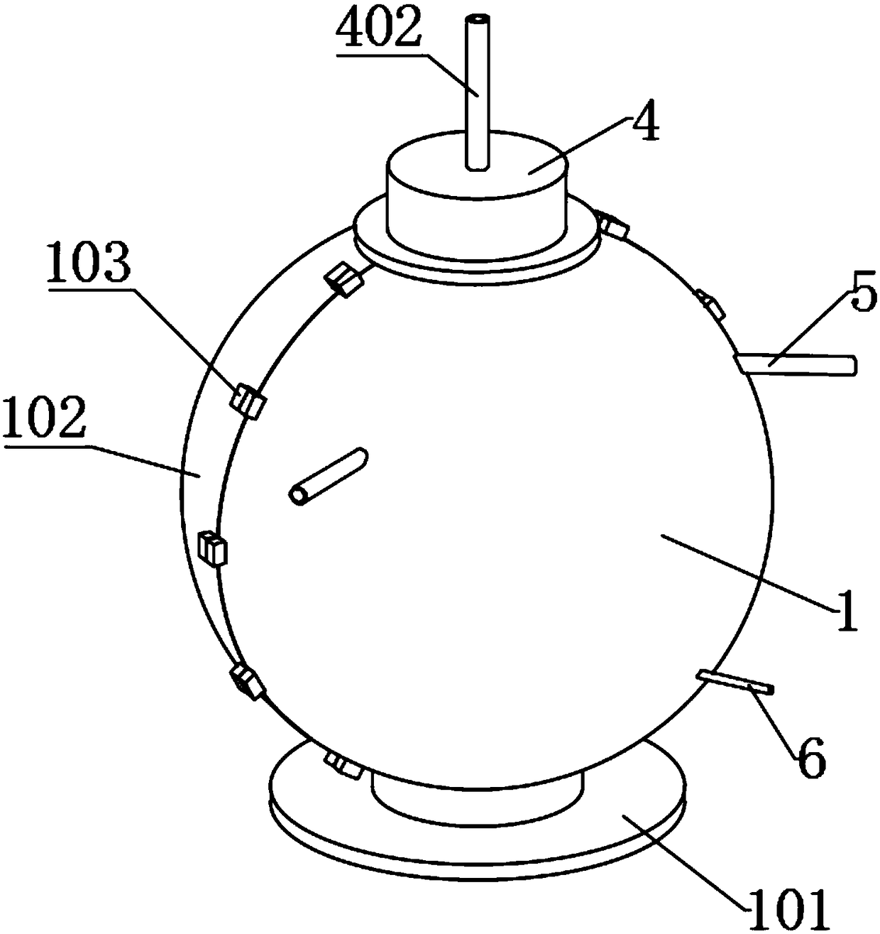
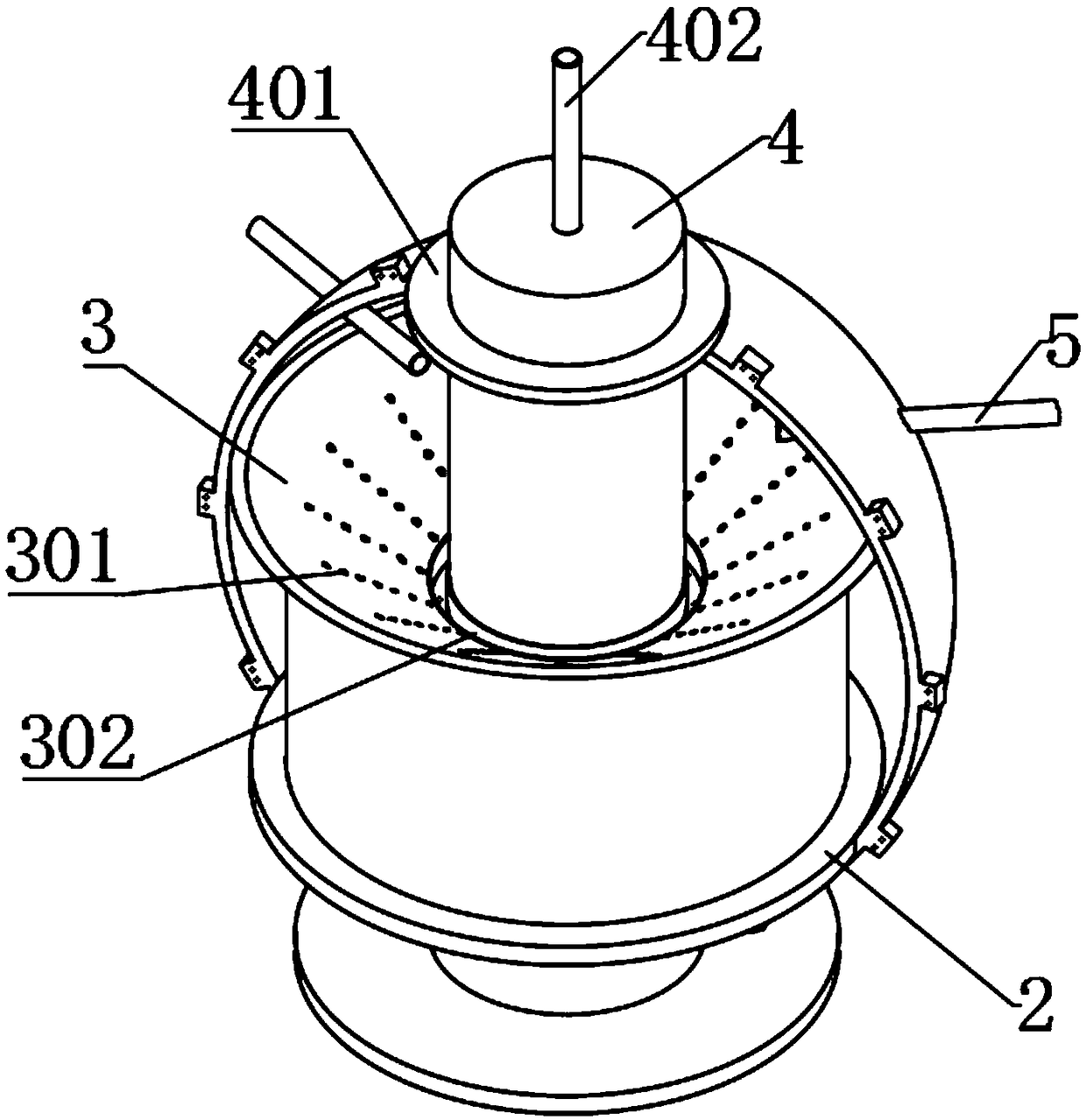
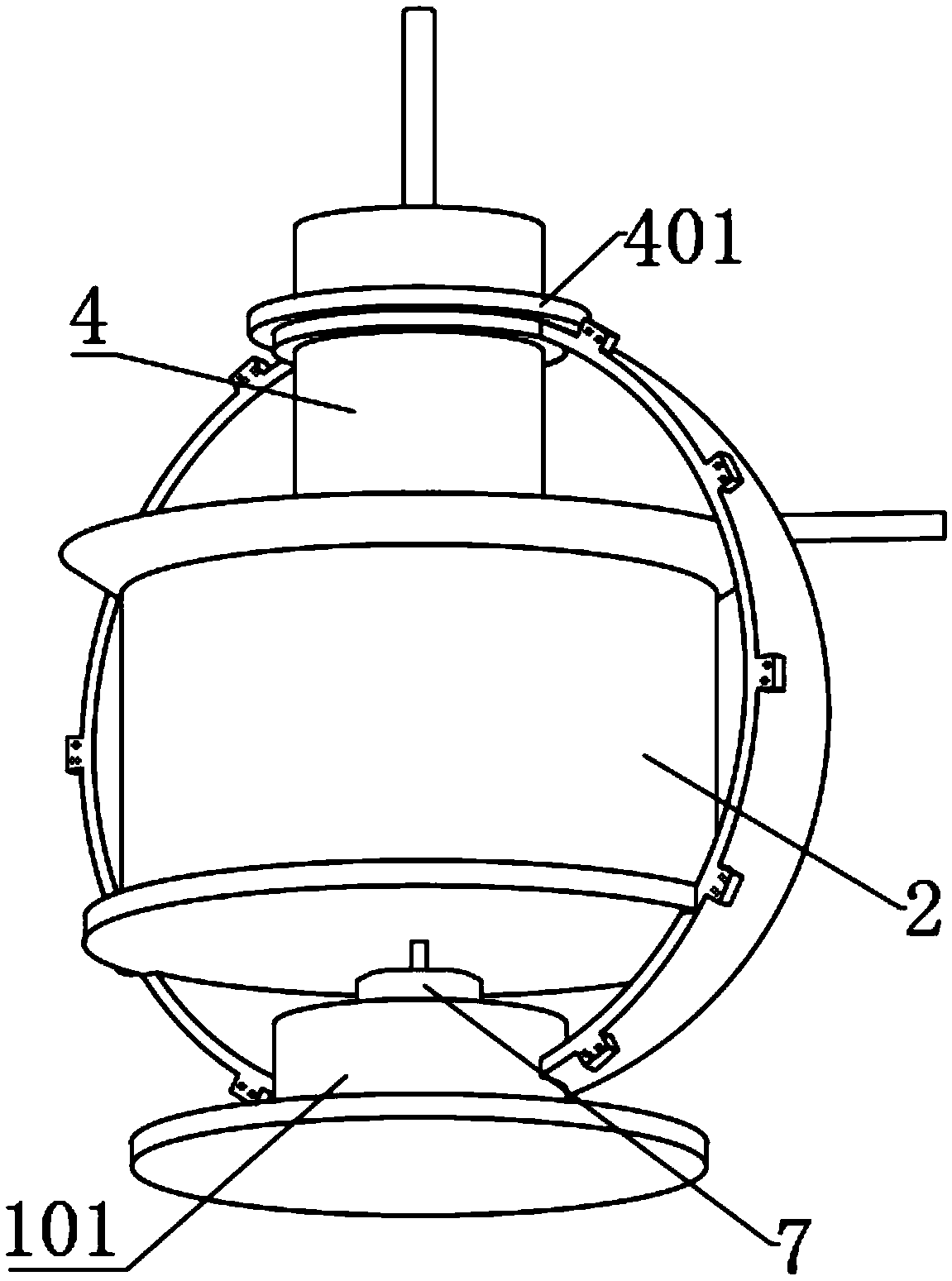
[0035] The present invention provides a water tank self-cleaning and disinfection device for environmental protection water treatment, comprising a tank body 1, a base 101, a hemispherical cover 102, a locking buckle 103, a circular water tank 2, a middle partition plate 201, a conical bucket 3, Filter hole 301, ring groove bucket 302, submersible pump shell 4, rubber cover 401, water outlet pipe 402, semicircular water inlet groove hole 403, water inlet pipe 5, disinfection gas pipe 6, gas emission hollow ball 601, stirring motor 7 and stirring blade 701; The inner lower end of the box body 1 is fixedly installed with a circular water tank 2, and the middle partition plate 201 is connected to the inner side of the circular water tank 2 through six groups of connecting plates. The upper end of the circular water tank 2 is provided with a conical shape. bucket 3, and the conical bucket 3 is provided with a plurali...


PUM

PropertyMeasurementUnit
thicknessaaaaaaaaaa

Abstract

The invention provides a water tank self-cleaning and disinfection device for environmental protection water treatment. The water tank self-cleaning and disinfection device comprises a round water storage groove, a gas diffusion hollow sphere and a stirring blade, wherein a tapered hopper is arranged at the upper end of the round water storage groove; a plurality of groups of filtering holes are annularly formed in the tapered hopper; an annular groove hopper is further connected to the middle of the bottom of the tapered hopper; six groups of semicircular water inlet groove holes are furtherformed in a bottom end side of a shell of a submersible pump; a stirring motor is fixed in a base; a rotary shaft penetrates through a bottom plate of the round water storage groove to be connected with the stirring balde; a disinfection air pipe penetrates into the round water storage groove and is arranged at the lower side of a middle separation plate; a semispherical cover is further buckled at an opening end of the box body through a locking buckle. The tapered hopper is arranged and the tapered hopper and the filtering holes in the annular groove hopper can be used for filtering so thatwater can fall into the round water storage groove; meanwhile, filtered impurities can fall into the annular groove hopper along the tapered hopper; the stirring motor is started to drive the stirringblade to stir so that the disinfection treatment effect is increased.

Description

technical field [0001] The invention belongs to the technical field of water treatment and environmental protection equipment, and more particularly relates to a water tank self-cleaning and disinfection device for environmental protection water treatment. Background technique [0002] At present, with the increasingly serious water pollution, a lot of water needs to be disinfected, so water tank sterilizers are more and more widely used, such as: self-provided water source disinfection, high-level water tanks, food industry water, circulating water systems, waterscape fountain pools , water plant clear water pool, living water tank, swimming pool, fire water tank, etc. [0003] The inventor found similar patents in the process of retrieving patents. For example, the Chinese patent with application number: 201520035406.3 discloses a water tank self-cleaning sterilizer, including an electric control cabinet arranged outside the water tank and an electric control cabinet arran...

Claims


Application Information

Patent Timeline
Patent Type & Authority Applications(China)
IPC IPC(8): C02F1/50C02F1/00
CPCC02F1/001C02F1/50
Inventor 程度
Owner 程度
Learn More