
Space phase compensation system in orbital angular momentum optical communication, and method thereof

A phase compensation, space optical communication technology, applied in transmission systems, free space transmission, electromagnetic wave transmission systems, etc., can solve the problems of high cost, complex technology, high precision requirements of optical components, achieve simple structure, improve signal-to-noise ratio, The effect of reducing the bit error rate

Pending Publication Date: 2018-10-26
SOUTH CENTRAL UNIVERSITY FOR NATIONALITIES
View PDF4 Cites 25 Cited by
  • Summary
  • Abstract
  • Description
  • Claims
  • Application Information

AI Technical Summary

Problems solved by technology

Adaptive optics systems are currently the most promising technology for compensating for wavefront distortion during imaging caused by atmospheric turbulence or other factors, and the system must use limited data to analyze and perform wavefront distortion every millisecond. Correction, although it does improve the communication effect, it requires high precision of optical components, complex technology, and high cost, so it is difficult to be widely used in actual communication occasions

Method used


Image

  • Space phase compensation system in orbital angular momentum optical communication, and method thereof
  • Space phase compensation system in orbital angular momentum optical communication, and method thereof
  • Space phase compensation system in orbital angular momentum optical communication, and method thereof

Examples


Embodiment Construction

[0050] The following will be described in detail in conjunction with the accompanying drawings and embodiments.

[0051] 1. System

[0052] 1. Overall

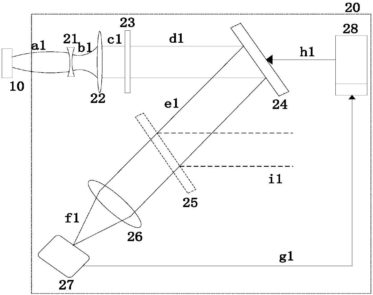
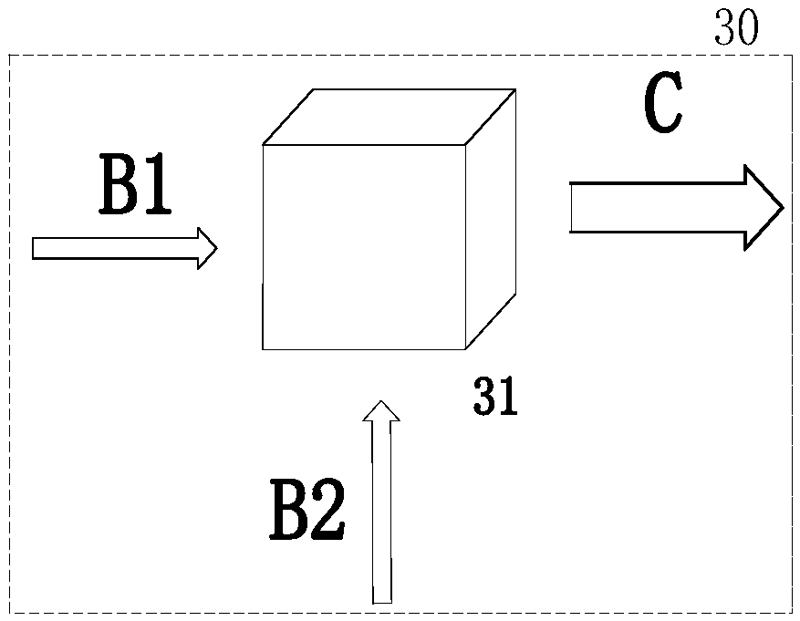
[0053] Such as figure 1 , the system includes sequentially connected light source 10, modulation OAM 20, mode multiplexing 30, free space 40, demodulation OAM 50 and coherent detection 60;

[0054]Based on the whole process of vortex beam spatial optical communication, this system uses iterative phase recovery algorithm at the sending end and receiving end to compensate any beam phase reflected by the liquid crystal spatial light modulator, and improves the vortex caused by the lack of existing technology and atmospheric turbulence. The symmetry of the rotating beam is not perfect, which improves the quality of the beam for subsequent use and transmission.

[0055] 2. Functional unit

[0056] 1) Light source 10

[0057] Use pulsed signal light with modulation format.

[0058] 2) Modulate OAM20

[0059] Such as figure ...


PUM


Abstract

The invention discloses a space phase compensation system in orbital angular momentum optical communication, and a method thereof, and relates to the liquid crystal space spatial modulation technology, and in particular to phase compensation of vortex beams in space optical communication. The system comprises a light source, a modulation OAM, mode multiplexing, a free space, a demodulation OAM andcoherent detection, which communicate with each other in sequence; and any beam phase reflected by a liquid crystal spatial light modulator is compensated on a sending end and a receiving end by using an iterative phase recovery algorithm, thereby improving the imperfect state of the symmetry of the vortex beams caused by atmosphere turbulence, improving the quality of the beams and facilitatingthe subsequent utilization and transmission.Compared with the prior art, the space phase compensation system disclosed by the invention realizes the phase distortion existing in a stepwise correctionspatial optical communication system, (2) improves the quality of the generated vortex beams and the quality of receiving demodulation to a certain extent,comprehensively improves the signal to noiseratio of the whole system and reduces the bit error rate; and the space phase compensation system is simple in structure and is easy to implement.

Description

technical field [0001] The invention relates to liquid crystal spatial light modulation technology, in particular to a spatial phase compensation system and method in orbital angular momentum optical communication, in particular to phase compensation for vortex beams in spatial optical communication. Background technique [0002] Beams with Orbital Angular Momentum (OAM) are called vortex beams, and vortex beams have a phase factor in is the direction angle, and l is the topological charge, that is, the number of times the wavefront rotates in one wavelength. In theory, l can be any integer, that is, it has infinitely many eigenstates. [0003] Since the use of vortex beams with different topological charges to realize mode multiplexing transmission information can greatly expand the system capacity and realize optical transmission with high spectral efficiency, so the preparation, transmission and reception of OAM beams have received extensive attention and research. wi...

Claims


Application Information

Patent Timeline
Patent Type & Authority Applications(China)
IPC IPC(8): H04B10/61H04B10/079H04B10/11
CPCH04B10/07953H04B10/11H04B10/6163H04B10/6165
Inventor 侯金余晓雪杨春勇陈少平
Owner SOUTH CENTRAL UNIVERSITY FOR NATIONALITIES
Learn More