A speed maintaining device and system for nuclear power feed water pump set

A technology of holding device and water supply pump, which is applied in the field of nuclear power generation, can solve the problems of insufficient water supply in the secondary circuit, reduce hydraulic coupler, control signal failure, etc., so as to avoid the situation of output speed fluctuation, avoid the problem of water supply fluctuation, and enhance the position The effect of maintaining ability

Active Publication Date: 2020-07-28
GUANGDONG NUCLEAR POWER JOINT VENTURE +4
View PDF6 Cites 0 Cited by
  • Summary
  • Abstract
  • Description
  • Claims
  • Application Information

AI Technical Summary

Problems solved by technology

[0004] At present, the spoon tube of the hydraulic coupler used does not have the function of maintaining the position of the telescopic position. In the process of water supply control, such as the failure of the position sensor of the spoon tube and the failure of the PLC controller, it is often used to adjust the three-position four-way The control signal of the servo solenoid valve is invalid, and the oil volume of the hydraulic cylinder cannot be maintained, so that the position of the spoon tube will automatically move to the 0% position, reducing the amount of oil in the working chamber of the hydraulic coupling. The spoon tube in this failure situation The "return to zero" switch position will cause the speed of the booster pump to drop instantaneously, resulting in insufficient water supply to the secondary circuit, causing the steam generator to shut down or shut down the nuclear power unit due to water level fluctuations.

Method used


Image

  • A speed maintaining device and system for nuclear power feed water pump set
  • A speed maintaining device and system for nuclear power feed water pump set
  • A speed maintaining device and system for nuclear power feed water pump set

Examples


Embodiment Construction

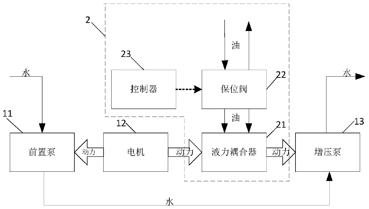
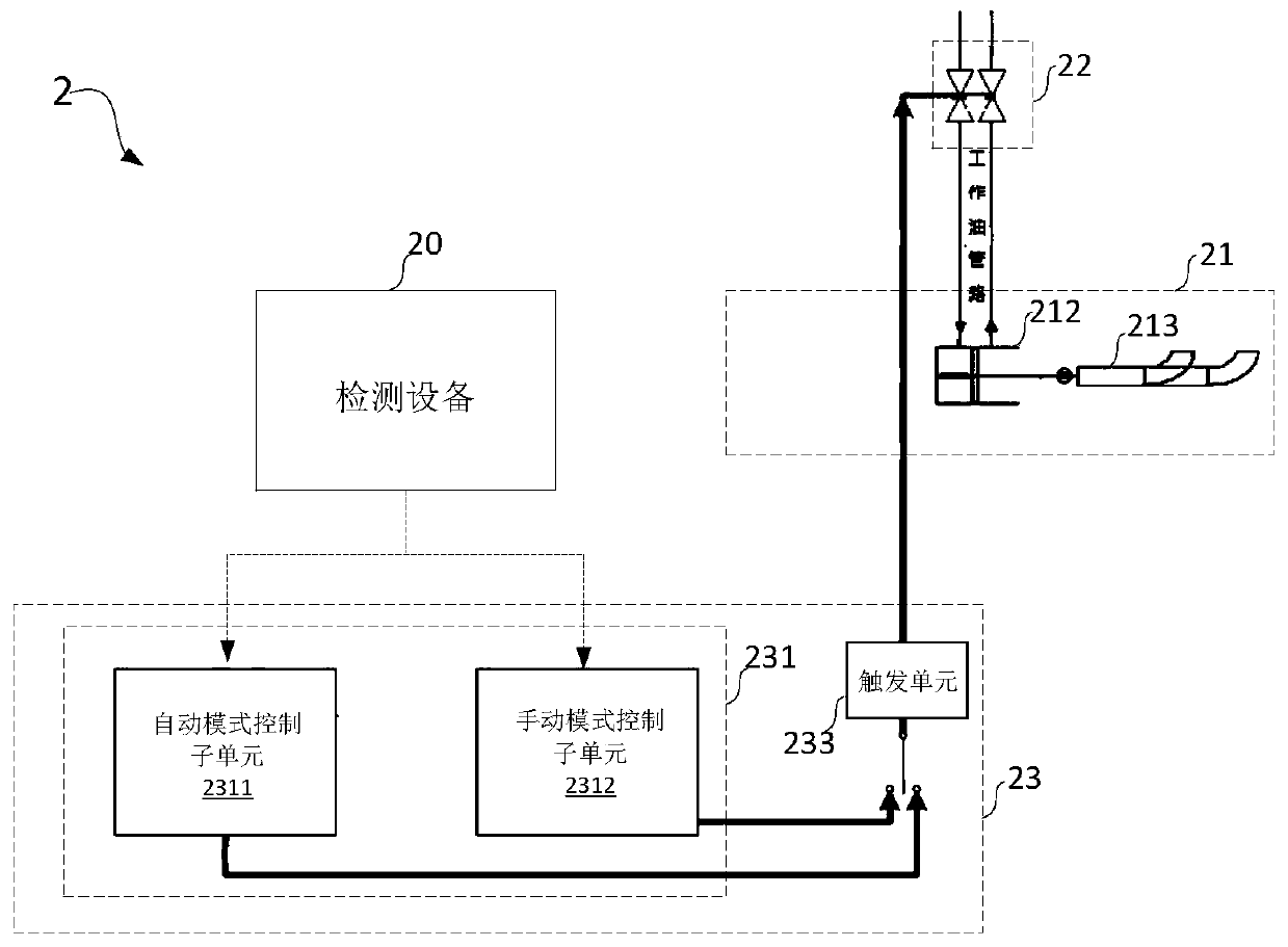
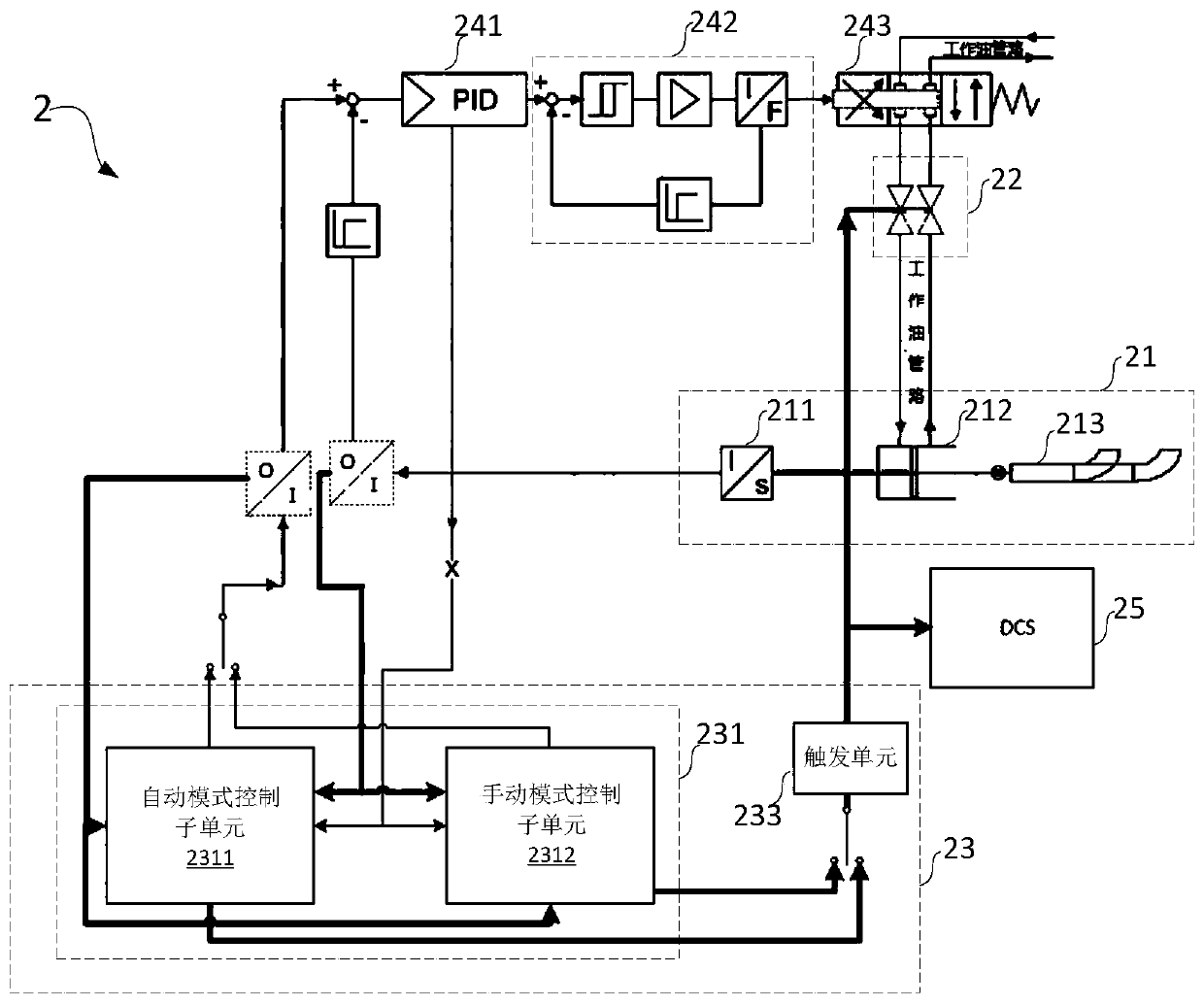
[0039] The present invention will be further described in detail below through specific embodiments in conjunction with the accompanying drawings. Wherein, similar elements in different implementations adopt associated similar element numbers. In the following implementation manners, many details are described for better understanding of the present application. However, those skilled in the art can readily recognize that some of the features can be omitted in different situations, or can be replaced by other elements, materials, and methods. In some cases, some operations related to the application are not shown or described in the description, this is to avoid the core part of the application being overwhelmed by too many descriptions, and for those skilled in the art, it is necessary to describe these operations in detail Relevant operations are not necessary, and they can fully understand the relevant operations according to the description in the specification and genera...


PUM


Abstract

The invention relates to a speed keeping device for a nuclear power water-feeding pump set and a nuclear power water-feeding pump set system. The speed keeping device comprises a hydraulic coupler, alockup valve, a controller and the like. Due to the fact that the retaining valve is arranged on an external oil supply pipeline of the hydraulic coupler, the hydraulic coupler in the nuclear power water-feeding pump set has a retention function, when the controller judges that a nuclear power unit has abnormal working conditions such as faults of a spoon tube position sensor in the hydraulic coupler or faults of the controller, the controller can control the retaining valve to cut off an oil path so that the position of a spoon tube in the hydraulic coupler can be kept, then the output rotating speed of the hydraulic coupler is kept unchanged, and the outward water supply amount of the nuclear power water-feeding pump set is kept unchanged. The nuclear power water-feeding pump set systemadopting the speed keeping device has the operational reliability in a fault state, so that that the situations that when the faults occur, the large fluctuation of the output rotating speed is causeddue to the fact that the position of the spoon tube automatically returns to the zero position, and then the unit transient sate is caused are effectively avoided, and enough barrier-removing intervention time is also reserved for workers.

Description

technical field [0001] The invention relates to nuclear power generation technology at the level of one million kilowatts, in particular to a speed maintaining device and system for a nuclear power feedwater pump set. Background technique [0002] Nuclear power generation is an important new energy power generation technology. Nuclear fission energy replaces the chemical energy of fossil fuels, nuclear reactors and steam generators replace thermal power boilers, and steam drives steam turbines to generate electricity. At present, nuclear power units mainly include nuclear reactors, steam generators, steam turbines, generators, and power regulation control systems. The important function of providing speed-adjusted water supply to the steam generator, and the feedwater pump set (or called APA pump) is the core component of the electric main water supply system, and it is necessary for the speed-regulated water supply process of the steam generator and even the safe and stable...

Claims


Application Information

Patent Timeline
Patent Type & Authority Patents(China)
IPC IPC(8): F04B49/06F04B49/10
CPCF04B49/06F04B49/10
Inventor 柴大虎黄新帅张世伟余进程王少龙
Owner GUANGDONG NUCLEAR POWER JOINT VENTURE
Why Eureka
Try Eureka