Ex-situ catalytic pyrolysis liquefaction system for biomass

A technology of catalytic pyrolysis and liquefaction system, applied in the field of biomass ex-situ catalytic pyrolysis and liquefaction system, can solve the problems of difficult separation of fluidized medium and catalyst, not being widely used and popularized, and high operating cost against gravity field, Achieve the effect of reducing coking inactivation, saving economic costs and low cost

Active Publication Date: 2018-11-02
SHANDONG UNIV OF TECH
View PDF7 Cites 3 Cited by
  • Summary
  • Abstract
  • Description
  • Claims
  • Application Information

AI Technical Summary

Problems solved by technology

The disadvantages of the fixed bed type mainly include problems such as uneven temperature distribution, poor heat transfer, weak raw material processing capacity, and inability to replace the catalyst; the fluidized bed type is difficult to separate the fluidized medium from the catalyst, and the operating cost of reverse gravity field transportation is relatively high. , has not been widely used and promoted in the biomass catalytic pyrolysis liquefaction process system

Method used


Image

  • Ex-situ catalytic pyrolysis liquefaction system for biomass
  • Ex-situ catalytic pyrolysis liquefaction system for biomass

Examples


Embodiment

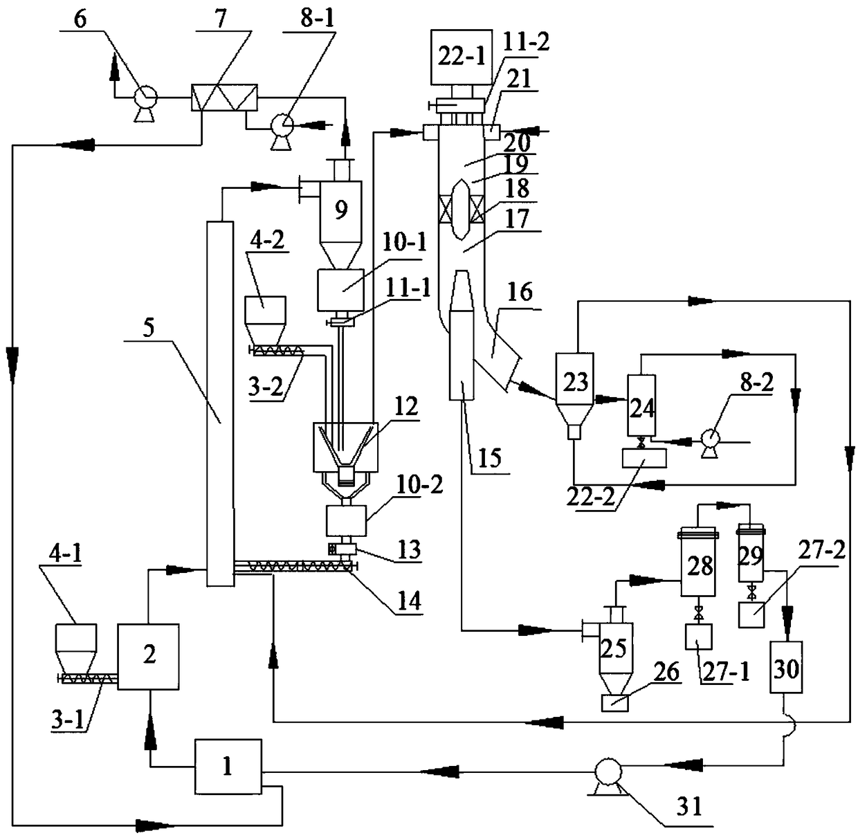
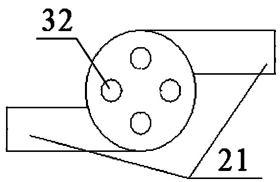
[0028] Such as figure 1 , figure 2 As shown, a biomass ex-situ catalytic pyrolysis liquefaction system includes a gasifier 2, a riser heater 5, a rotating cone reactor 12, a diversion cyclone reactor 19, a catalyst regeneration system, and a gas-solid separator 25 and condensing system.

[0029] The bottom of the gasifier 2 is connected to the first biomass feeder 3-1, the first biomass feeder 3-1 is connected to the first biomass hopper 4-1, the upper part of the gasifier 2 is connected to the riser heater The lower part of 5 is connected by a gas phase pipeline, the quartz sand feeder 14 is connected with the lower part of the riser heater 5, and the quartz sand feeder 14 is a screw feeder. The upper part of the riser heater 5 is connected to the inlet of the quartz sand separator 9, the lower part of the quartz sand separator 9 is connected to the heated sandbox 10-1, and the lower part of the heated sandbox 10-1 is connected to the inlet of the rotary cone reactor 12. ...


PUM


Abstract

The invention relates to the technical field of conversion and utilization of biomass energy, in particular to an ex-situ catalytic pyrolysis liquefaction system for biomass. The ex-situ catalytic pyrolysis liquefaction system comprises a gasifier, a riser heater, a rotating cone reactor, a flow-guide cyclone reactor, a catalyst regeneration system, a gas-solid separator and a condensation system,wherein the bottom of the gasifier is connected with a first biomass feeder, and the upper part of the gasifier is connected with the lower part of the riser heater; a quartz sand feeder is connectedwith the lower part of the riser heater; the upper part of the riser heater is connected with an inlet of a quartz sand separator; the lower part of the quartz sand separator is connected with a heated sand box which is connected with an inlet of the rotating cone reactor; an outlet of the rotating cone reactor is connected with a gas inlet of the flow-guide cyclone reactor through a gas pipe; the flow-guide cyclone reactor is connected with a catalyst box at the upper part through catalyst inlets. An ex-situ catalytic pyrolysis process is performed on biomass with the system, operation is convenient and controllable, and working condition parameters in a pyrolysis process and a catalytic cracking process can be adjusted and controlled respectively.

Description

technical field [0001] The invention relates to the technical field of biomass energy conversion and utilization, in particular to a biomass non-situ catalytic pyrolysis liquefaction system. Background technique [0002] Fossil energy currently accounts for more than 80% of the world's primary energy supply, but because of its non-renewability and many environmental problems incidental to the development and utilization process, it has restricted the sustainable development of human beings. Therefore, the research on new energy has become an important field of energy development today. It can not only alleviate the dependence on fossil energy, but also have great significance for environmental protection and sustainable development of human society. It is an inevitable trend in the world. [0003] Among them, biomass energy uses plants with energy value and organic waste as raw materials. It has the characteristics of rich resources and renewable resources. It is currently t...

Claims


Application Information

Patent Timeline
Patent Type & Authority Applications(China)
IPC IPC(8): C10B53/02C10G1/00C10J3/20C10J3/72
CPCC10B53/02C10G1/00C10J3/20C10J3/72Y02E50/10Y02P20/584
Inventor 张玉春付鹏李志合易维明蔡红珍李永军王娜娜
Owner SHANDONG UNIV OF TECH
Why Eureka
Try Eureka