

Catalytic converter and method of assembly thereof
A technology for a catalytic converter and an assembly method, applied in the field of catalytic converters and their assembly, can solve the problems of exhaust gas leakage, uneven thickness, membrane deformation and the like
- Summary
- Abstract
- Description
- Claims
- Application Information
AI Technical Summary
Problems solved by technology
Method used
Image

Examples
no. 1 example
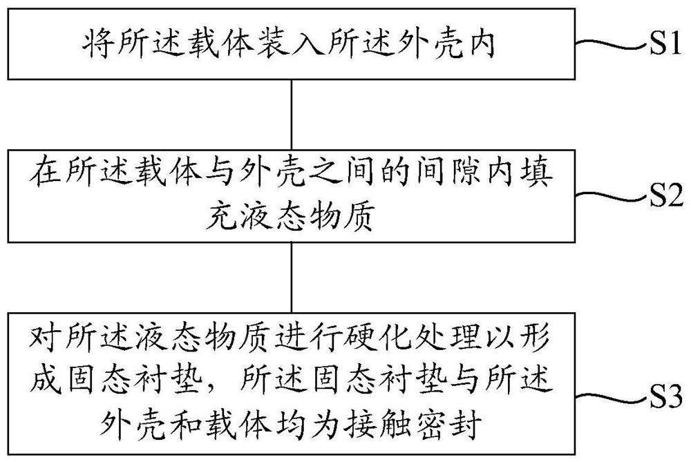
[0045] This technical solution provides a method for assembling a catalytic converter, referring to figure 1 , the assembly method includes:
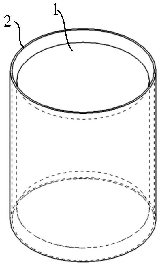
[0046] Execute step S1 and combine figure 2 , provide the carrier 1 and the shell 2, and put the carrier 1 into the shell 2, at this time, there is a gap between the carrier 1 and the shell 2;
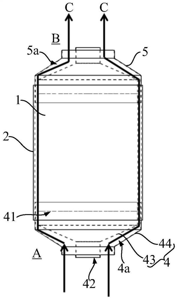
[0047] Execute step S2 and combine image 3 , fill the gap between the carrier 1 and the shell 2 with a liquid substance, and the liquid substance flows along the arrow C;
[0048] Execute step S3 and combine Figure 4 , hardening the liquid substance to form a solid liner 3 , which is in contact with the shell 2 and the carrier 1 .
[0049] Compared with directly wrapping the film on the outside of the carrier, the liquid substance has good gap filling properties, and can form a good bond with the surface of the carrier 1 and the shell 2 to a certain extent, and the liquid substance can cover the surface of the carrier 1 and the shell 2, ...
no. 2 example
[0065] In this technical solution, the method for filling the liquid substance in the gap between the carrier and the shell may include:
[0066] refer to Figure 6 , providing a soft bag 6, the soft bag 6 has a solution inlet 6a;
[0067] refer to Figure 7 , before loading the carrier 10 into the shell 20, put the carrier 1 into the soft bag 6;
[0068] Put the soft bag 6 with the carrier 10 into the casing 20, the casing 20 has openings at both ends along the depth direction, and the solution inlet 6a can protrude from one end of the casing 20;
[0069] Inject a liquid substance into the soft bag 6 from the solution inlet 6a, so that the soft bag 6 expands outward to contact and seal with the shell 20 along the circumferential direction of the carrier 10;
[0070] refer to Figure 8 , heating in the process of hardening treatment, soft bag 6 (refer to Figure 7 ) is melted by heat and blended into the solid liner 30.
[0071] refer to Figure 7 , during the process o...
no. 3 example
[0080] Different from the first embodiment and the second embodiment, refer to Figure 9 , in this technical solution, the liner 300 is a thread wound helically on the surface of the carrier 100 . During the assembly process, the wire is wound along the outer surface of the carrier 100 to form the liner 300; after that, the carrier 100 can be rotated around the helical axis of the liner 300, so that the friction force between the wire and the inner wall of the housing 200 is along the line. The distribution of the helical direction, which can well avoid the circumferential wrinkling of the wire during the assembly process, resulting in gaps.
[0081] Therefore, different from wrapping the entire layer of film on the carrier 100 in the prior art, the liner 300 in this technical solution is spirally wound, which can more effectively solve the problem of the gap formed between the carrier 100 and the casing 200 .
[0082] The thread may be a high temperature resistant material s...
PUM
 Abstract
Description
Claims
Application Information