
High-temperature alloy smelting device

A technology for smelting equipment and high-temperature alloys, which is applied in the field of high-temperature alloy smelting equipment to achieve the effects of increasing heating temperature, wide selection range, and wide application range

Inactive Publication Date: 2018-11-02
孟静
View PDF10 Cites 0 Cited by
  • Summary
  • Abstract
  • Description
  • Claims
  • Application Information

AI Technical Summary

Problems solved by technology

These all pose challenges to the traditional metal resistance heating method

Method used


Image

  • High-temperature alloy smelting device
  • High-temperature alloy smelting device
  • High-temperature alloy smelting device

Examples


Embodiment Construction

[0018] The technical solutions in the embodiments of the present invention are clearly and completely described below in conjunction with the accompanying drawings in the embodiments of the present invention. Obviously, the described embodiments are only part of the embodiments of the present invention, not all of them. Based on the embodiments of the present invention, all other embodiments obtained by persons of ordinary skill in the art without making creative efforts belong to the protection scope of the present invention.

[0019] In the following description, a lot of specific details are set forth in order to fully understand the present invention, but the present invention can also be implemented in other ways different from those described here, and those skilled in the art can do it without departing from the meaning of the present invention. By analogy, the present invention is therefore not limited to the specific examples disclosed below.

[0020] Such as Figure...


PUM


Abstract

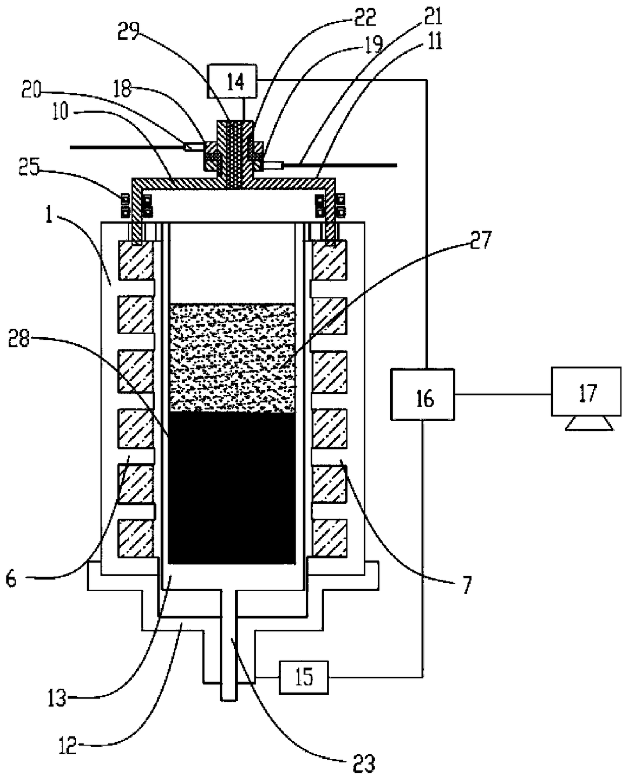
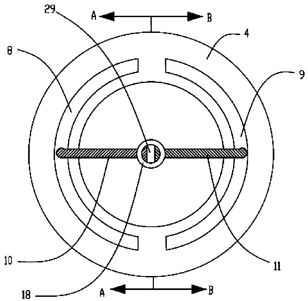
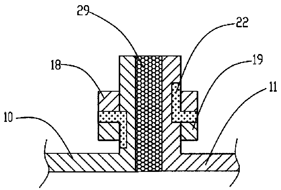
The invention discloses a high-temperature alloy smelting device and relates to the technical field of smelting devices of alloys. According to the device, a liquid melt is placed in a liquid resistorcarrier by means of a centrifugal force, and a liquid resistor is electrified in a movement condition through a rotary electrode, so that the liquid resistor heats; and then a directional freezing device is controlled by controlling the shape of the liquid resistor or movement of a crucible. According to the device and a method, the liquid melt which is high in boiling point is taken as the resistor, so that the heating temperature can be improved greatly, and meanwhile, the high boiling point liquid melt can be a metal melt and a non-metal melt, so that the selecting range of the liquid resistor is wide. The symmetry of a temperature field in the rotating condition is relatively high. The shape of the rotary liquid resistor can be changed at will according to the shape of the liquid resistor carrier, so that the processing difficulty and the processing cost of a solid resistor are reduced greatly.

Description

technical field [0001] The invention relates to the technical field of alloy smelting devices and methods, in particular to a high-temperature alloy smelting device. Background technique [0002] For superalloys, it is ideal to use electromagnetic field for heating, and the heating temperature is high. However, electromagnetic field induction melting has a strong stirring effect on the melt, and it is difficult to establish a steady-state directional solidification temperature field, so it is best to use resistance heating. For the smelting of non-metallic alloys, since their solids are usually non-conductive, resistance heating must be selected to control the melting, directional solidification and crystal growth of raw materials. This requires a resistance heater with a large calorific value and a high heat-resistant temperature to heat the metal or non-metal melt. Since metal resistors have a fixed melting point, the heating temperature is limited, especially for the hi...

Claims


Application Information

Patent Timeline
IPC IPC(8): F27B14/06F27B14/14F27D11/04C22C1/02
CPCF27B14/06C22C1/02F27B14/14F27B2014/068F27D11/04F27M2003/13
Inventor 孟静
Owner 孟静
Learn More