Novel power factor correction device

A power factor correction, a new type of technology, applied in output power conversion devices, climate sustainability, high-efficiency power electronic conversion and other directions, can solve the problems of small voltage fluctuation range, unfavorable capacitor energy storage, etc. The effect of low device cost and reduced capacitance

Inactive Publication Date: 2018-11-02
NANJING UNIV OF SCI & TECH
View PDF2 Cites 6 Cited by
  • Summary
  • Abstract
  • Description
  • Claims
  • Application Information

AI Technical Summary

Problems solved by technology

In the traditional shunt capacitor filtering scheme, the capacitor voltage is the DC bus voltage,

Method used


Image

  • Novel power factor correction device
  • Novel power factor correction device
  • Novel power factor correction device

Examples


Embodiment Construction

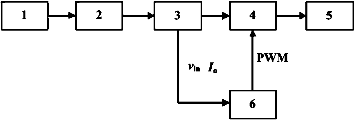
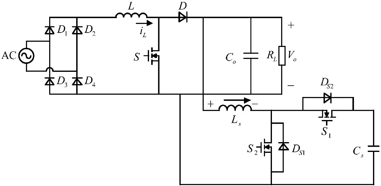
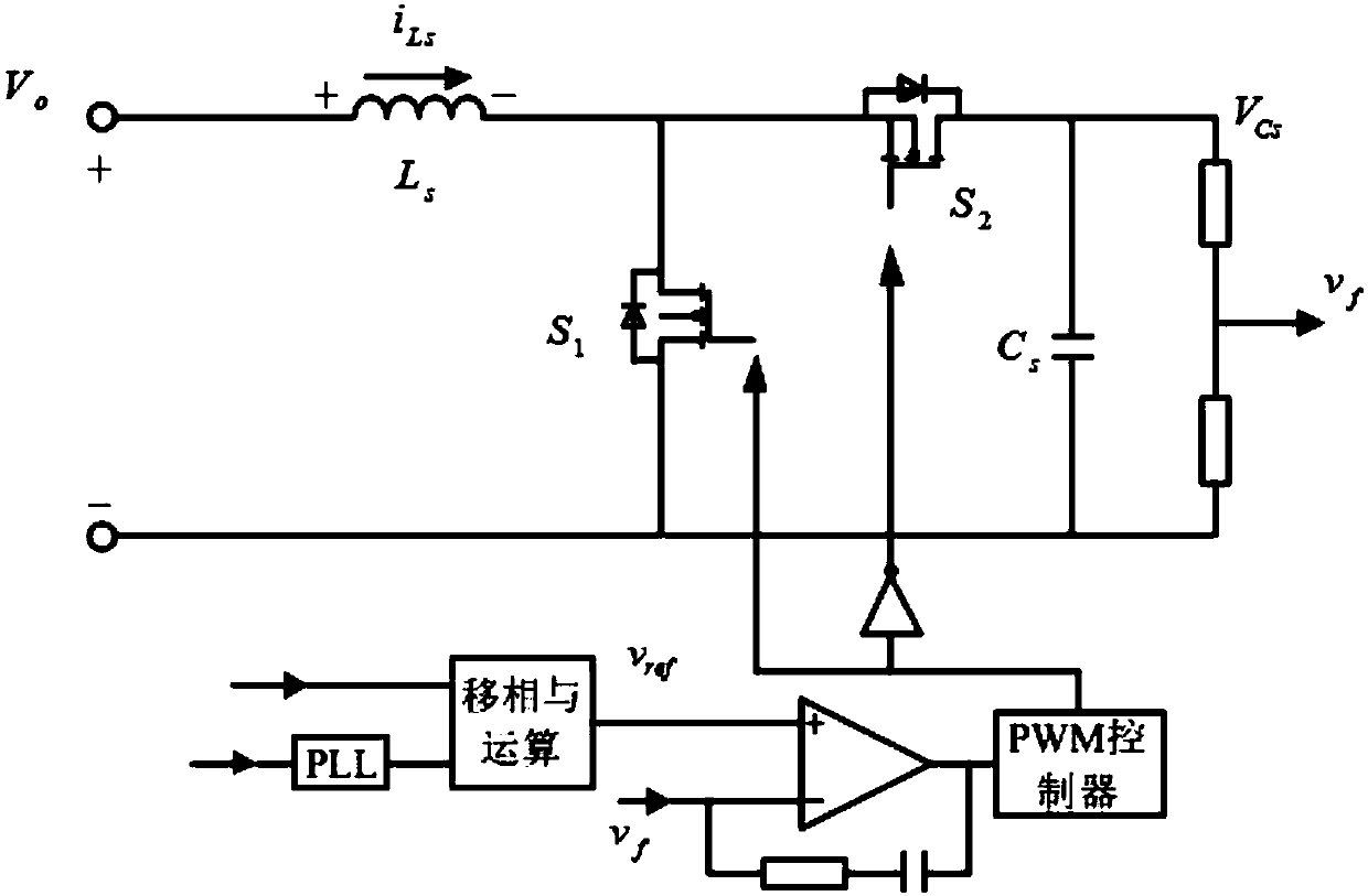
[0015] In conjunction with the accompanying drawings, a novel power factor correction device of the present invention includes an AC source 1, a rectifier bridge circuit 2, a Boost circuit 3, a decoupling circuit 4, a load 5 and a control circuit 6, and the AC source 1 The output terminal is connected to the input terminal of the rectifier bridge 2, and the signal output by the AC source 1 passes through the rectifier bridge circuit 2 and becomes steamed bun wave, which is used as the input of the Boost circuit 3, and the output terminal of the rectifier bridge circuit 2 is connected to the input terminal of the Boost circuit 3, The output terminal of the Boost circuit 3 is connected to the decoupling circuit 4, and the other terminal of the decoupling circuit 4 is connected to the load 5, wherein the decoupling circuit 4 is connected to the output capacitor C of the Boost circuit 3 o The control circuit 6 receives the signal from the Boost circuit 3 and outputs the signal to t...


PUM


Abstract

The invention discloses a novel power factor correction device, comprising an AC (alternating current) source, a rectifier bridge circuit, a Boost circuit, a decoupling circuit, a load and a control circuit, wherein the output end of the AC (alternating current) source is connected to the input end of a rectifier bridge, a signal is converted into steamed bun waves after being processed by the rectifier bridge circuit and serves as the input end of the Boost circuit, the output end of the Boost circuit is connected with the load, the decoupling circuit is connected in parallel with the front end of an output capacitor Co of the Boost circuit, and the control circuit outputs the signal to the decoupling circuit. According to the scheme of the invention, the ripple power in an AC/DC power conversion device or a DC/AC power conversion device is transferred to a decoupling capacitor, and thus the limitation of DC bus voltage ripples can be broken; and a feedforward control strategy is adopted, and the compensation effect of a bidirectional Buck/Boost power decoupling circuit can be greatly improved. Based on the above advantages, a compensation circuit is added to a conventional powerfactor correction circuit, and thus the capacitance value of the output capacitor can be reduced, and the power factor correction of non-polarized electrolytic capacitors can be realized.

Description

technical field [0001] The invention relates to the technical field of power electronic converters, in particular to a power factor correction converter without electrolytic capacitors. Background technique [0002] In AC / DC and DC / AC converters, if the AC side voltage and current are both sine waves, the AC side power consists of two parts, the DC component and the AC component, so that the DC side voltage fluctuates at twice the AC frequency. In order to meet the voltage ripple requirements and absorb the pulsating power in the circuit, it is often necessary to connect a large-capacity electrolytic capacitor in parallel on the DC side. Taking LED lighting and photovoltaic power generation as an example, in order to meet the harmonic requirements of the IEC61000-3-2 standard, lighting fixtures usually use a drive power supply with power factor correction, and the input power changes instantaneously, while the output power is flat; The IEEE1547 standard also stipulates the ...

Claims


Application Information

Patent Timeline
IPC IPC(8): H02M1/42
CPCH02M1/42H02M1/4225Y02B70/10
Inventor 云珂王邦兴夏义徐波顾伟
Owner NANJING UNIV OF SCI & TECH
Why Eureka
Try Eureka