
Workpiece surface treatment method and terminal shell

A technology of workpiece surface and processing method, applied in the direction of electrical digital data processing, surface reaction electrolytic coating, digital data processing parts, etc. Large and other problems, to achieve the effect of avoiding step difference, avoiding knife pick marks, and high engraving accuracy

Pending Publication Date: 2018-11-06
BEIJING XIAOMI MOBILE SOFTWARE CO LTD
View PDF7 Cites 4 Cited by
  • Summary
  • Abstract
  • Description
  • Claims
  • Application Information

AI Technical Summary

Problems solved by technology

[0004] However, when using the technology in the prior art, when the anode layer is broken on the surface of the metal substrate, due to the large cutting capacity of the CNC milling cutter, it is very easy to form a large step difference on the surface of the metal substrate, resulting in the surface of the metal substrate There are obvious traces of cutting

Method used


Image

  • Workpiece surface treatment method and terminal shell
  • Workpiece surface treatment method and terminal shell
  • Workpiece surface treatment method and terminal shell

Examples


Embodiment 1

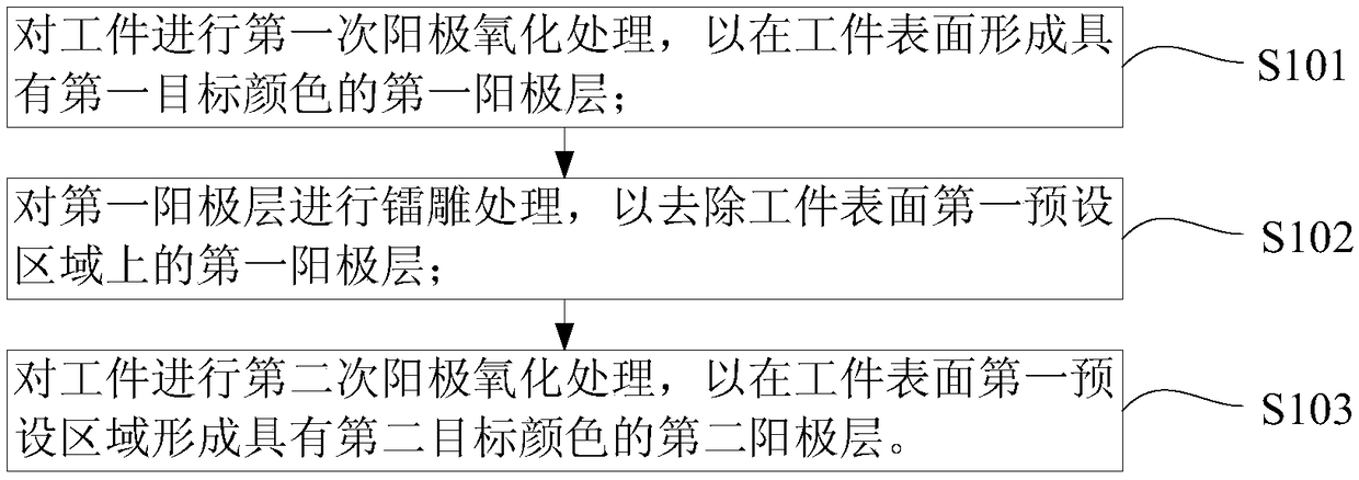
[0042] figure 1 It is a flow chart of a workpiece surface treatment method shown according to an exemplary embodiment; figure 2 is a partial cross-sectional view of the workpiece after the first anodizing treatment shown according to an exemplary embodiment; image 3 is a schematic structural view of a workpiece after laser engraving according to an exemplary embodiment; Figure 4 is a partial cross-sectional view of a workpiece after the second anodizing treatment according to an exemplary embodiment.

[0043] like figure 1 shown, combined with Figure 2-4 , the workpiece surface treatment method comprises the steps of:

[0044] S101, performing a first anodic oxidation treatment on the workpiece to form a first anode layer with a first target color on the surface of the workpiece;

[0045] The workpiece 1 is a semi-finished product that has been formed but not colored, and the finished product formed after the surface treatment method of the workpiece can be the casing...

Embodiment 2

[0110] Figure 9 It is a schematic diagram showing a partial structure of a terminal housing according to an exemplary embodiment.

[0111] like Figure 9 As shown, the embodiment of the present disclosure provides a terminal housing, which is made by using the workpiece surface treatment method provided in Embodiment 1.

[0112] In the embodiment of the present disclosure, the terminal housing is formed from a workpiece that has been formed but not colored, and is formed after the workpiece surface treatment method of the embodiment of the disclosure, which includes: a first anode layer 2 with a first target color, A second anode layer 3 having a second target color and a third anode layer 4 having a third target color.

[0113] In the embodiment of the present disclosure, the terminal casing may be a casing of a terminal such as a smart phone, a tablet, or a notebook, that is, a body, and may be made of metal aluminum or an aluminum alloy.


PUM


Abstract

The invention relates to a workpiece surface treatment method and a terminal shell, and belongs to the technical field of workpiece surface treatment. According to the workpiece surface treatment method and the terminal shell, a first anode layer with a first target color on the surface of a workpiece is subjected to laser carving treatment, so that the first anode layer at a first preset area onthe surface of the workpiece is removed, the first preset area on the surface of the workpiece is exposed out so that the workpiece can be subjected to secondary anodic oxidation treatment, and a second anode layer with a second target color is formed at the first preset area on the surface of the workpiece. Moreover, the controllability of carving strength is good in the laser carving treatment process, carving precision is high, and therefore segment gaps on the surface of the workpiece can be reduced and even avoided, machined traces on the surface of the workpiece are avoided and the visual effect of the workpiece is improved.

Description

technical field [0001] The present disclosure relates to the technical field of workpiece surface treatment, in particular to a workpiece surface treatment method and a terminal housing. Background technique [0002] With the widespread use of terminals such as smart phones and tablet devices, users have higher and higher requirements for richer terminal appearances. At present, in order to satisfy users' demands for rich appearances, taking a smart phone as an example, different colors are usually matched on the body of the smart phone. [0003] In related technologies, smartphones usually use a metal body with two colors, which is specifically realized through the following process: after anodizing the metal substrate once, an anode layer with one color is formed on the surface of the metal substrate; the anode layer is removed by CNC After breaking the anode layer of the metal substrate after the primary anode, and then performing a second anode on the metal substrate, t...

Claims


Application Information

Patent Timeline
Patent Type & Authority Applications(China)
IPC IPC(8): C25D11/12C25D11/14C25D11/18H04M1/02G06F1/16
CPCH04M1/0283G06F1/1633C25D11/022C25D11/12C25D11/14C25D11/18
Inventor 范金林肖志强孙坤
Owner BEIJING XIAOMI MOBILE SOFTWARE CO LTD
Learn More