
Low energy consumption denitration system for sintering smoke and technology

A technology of sintering flue gas and low energy consumption, applied in the field of sintering flue gas treatment, can solve the problems of unconsidered energy consumption, insufficient consideration, and large energy consumption, so as to ensure reliable operation of the system, reduce injection volume, and reduce energy consumption Effect

Pending Publication Date: 2018-11-06
BEIJING JINGCHENGKELIN ENVIRONMENTAL PROTECTION TECH +1
View PDF5 Cites 0 Cited by
  • Summary
  • Abstract
  • Description
  • Claims
  • Application Information

AI Technical Summary

Problems solved by technology

However, the reaction temperature required by LSCR is still higher than that of flue gas after sintering and desulfurization, which is about 70°C, and it needs to consume a lot of energy to ensure the effective denitrification reaction.
[0004] At present, domestic technical research on sintering flue gas denitrification either does not consider this part of energy consumption, or does not consider it sufficiently, resulting in energy waste

Method used


Image

  • Low energy consumption denitration system for sintering smoke and technology

Examples


Embodiment 1

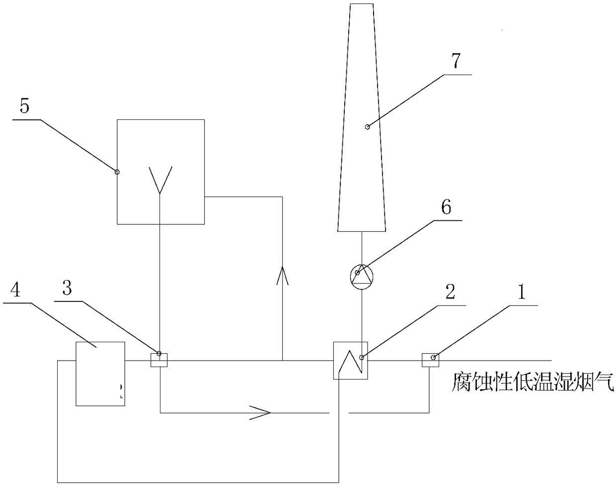
[0047] This embodiment provides a low energy consumption sintering flue gas denitrification system, the structural diagram of the system is as follows figure 1 shown, from figure 1 It can be seen from the figure that the system includes a primary heating device 1, a flue gas heating heat exchanger 2, a secondary heating device 3, a denitrification device 4, a hot flue gas generating device 5, a pressurized fan 6 and a chimney 7;

[0048] The primary heating device 1 is provided with a first flue gas inlet, a second flue gas inlet, and a flue gas outlet; The flue gas outlet of the device 1 passes through the flue gas heating heat exchanger 2 (the first flue gas inlet and the first flue gas outlet) and the secondary heating device 3 (the first flue gas inlet and the first flue gas outlet) in sequence through the pipeline It is connected with the flue gas inlet of the denitrification device 4; the flue gas outlet of the denitrification device 4 is connected with the second flue ...

Embodiment 2

[0053] This embodiment provides a low-energy sintering flue gas denitrification process, wherein the process is realized by using the low-energy sintering flue gas denitrification system provided in Example 1, and the process includes the following specific steps:

[0054] (1) Sintering flue gas (such as low-temperature wet sintering flue gas containing acid corrosive gas) enters the primary heating device 1 through the pipeline through its first flue gas inlet, and is initially heated in the primary heating device 1 The sintering flue gas is used to remove moisture in the flue gas and avoid acid corrosion;

[0055] (2) Exchange heat between the high-temperature purified flue gas obtained after the denitrification treatment and the sintered flue gas obtained in step (1) in the flue gas heating heat exchanger 2, so that the sintered flue gas is heated to about 150 ° C again, and then cooled The final high-temperature purified flue gas (its temperature is about 110°C) is dischar...


PUM


Abstract

The invention provides a low energy consumption denitration system for sintering smoke and technology. The system comprises a first-level warming device, a smoke warming heat exchanger, a second-levelwarming device and a denitration device. The sintering smoke enters the first-level warming device through pipelines. A smoke outlet of the first-level warming device is connected with a smoke outletof the denitration device through pipelines via the smoke warming heat exchanger and the second-level warming device successively. The smoke outlet of the denitration device is connected with a second smoke inlet of the smoke warming heat exchanger through pipelines. According to the low energy consumption denitration system for the sintering smoke and the technology, waste heat of the sinteringsmoke is taken into full consideration and utilized so that denitration can be conducted; the system is guaranteed to operate reliably through supplementary heating of the warming devices; and denitration energy consumption of the sintering smoke is lowered with the greatest possibility.

Description

technical field [0001] The invention relates to a low energy consumption sintering flue gas denitrification system and process, belonging to the technical field of sintering flue gas treatment. Background technique [0002] The iron and steel industry is a pillar industry of my country's national economy and a basic industry, but the iron and steel industry is also a high energy consumption and high pollution industry. NO x It is one of the main sources of air pollution in steel mills, and the sintering machine NO x Emissions account for about 100% of the total NO x 50%-60% of emissions, which is steel mill NO x Emission main unit. NO x It will cause acid rain and photochemical smog pollution, destroy the ozone layer, seriously damage the ecological environment, and endanger human health. Therefore, reducing NO in steel mills x Emissions, especially NO from sinter plants x Emissions are imperative. In June 2017, the Ministry of Environmental Protection of the People...

Claims


Application Information

Patent Timeline
Patent Type & Authority Applications(China)
IPC IPC(8): F27D17/00B01D53/86B01D53/90
CPCB01D53/8625B01D53/90F27D17/00F27D17/004F27D17/008B01D2258/0283
Inventor 杨源满信保定杨明华焦红蕾周靖张金成范硕温志刚
Owner BEIJING JINGCHENGKELIN ENVIRONMENTAL PROTECTION TECH
Learn More