
A CO for waste heat recovery from high temperature flue gas Cyclic cogeneration system

A technology of cogeneration and high temperature flue gas, which is applied in steam application, machine/engine, combined combustion mitigation, etc. It can solve the problems of insufficient heat source utilization and low overall system efficiency, so as to improve energy utilization efficiency, reduce volume and Occupy area, improve the effect of heat exchange matching

Active Publication Date: 2021-07-23
山西山安蓝天节能科技股份有限公司
View PDF5 Cites 0 Cited by
  • Summary
  • Abstract
  • Description
  • Claims
  • Application Information

AI Technical Summary

Problems solved by technology

[0005] The purpose of the present invention is to provide a cascade CO 2 Circulating combined heat and power system to solve conventional CO under variable temperature heat source 2 The power cycle has problems such as insufficient utilization of heat sources and low overall system efficiency. Improve the heat exchange matching between the cycle and the variable temperature heat source, effectively use the sensible heat of the cycle heat release process, and further improve the overall thermal energy utilization efficiency of the system.

Method used


Image

  • A CO for waste heat recovery from high temperature flue gas  <sub>2</sub> Cyclic cogeneration system
  • A CO for waste heat recovery from high temperature flue gas  <sub>2</sub> Cyclic cogeneration system

Examples


Embodiment Construction

[0018] The present invention will be further described below in conjunction with drawings and embodiments. Obviously, the implementation method described is only one of the preferred implementation methods of the present invention, and the present invention is not limited to the disclosed specific implementation methods, and all simple modifications and changes made to the following examples according to the technical essence of the present invention belong to The protection scope of the present invention.

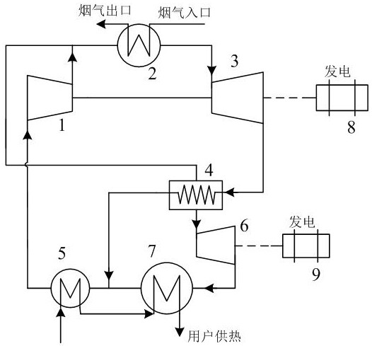
[0019] figure 1 shows the CO used for high temperature flue gas waste heat recovery according to an embodiment of the present invention 2 Schematic diagram of the structure of a cycle cogeneration system. Such as figure 1 As shown, the system mainly includes: compressor 1, supercritical heater 2, first turboexpander 3, second turboexpander 4, condenser 5, gas cooler 6, regenerator 7, second A generator 8, a second generator 9 and a heating circuit.

[0020] The outlet...


PUM


Abstract

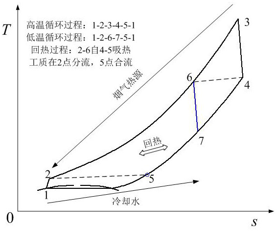
The invention discloses a CO used for recovery of waste heat from high-temperature flue gas 2 Cyclic cogeneration system. The system includes: a compressor, a supercritical heater, a first turboexpander, a second turboexpander, a regenerator, a condenser, a gas cooler and a generator. The system uses CO 2 As a working fluid, the endothermic process is located at supercritical pressure. The cycle process includes high-temperature power cycle, low-temperature power cycle and hot water supply cycle. The high-temperature power cycle absorbs heat from high-temperature flue gas, and the low-temperature power cycle absorbs heat from high-temperature cycle expansion exhaust steam. The low-temperature power cycle exhaust steam is used as a heat source for heat supply. It can output electric energy and provide users with 50~80 o The hot water of C realizes cogeneration of heat and power. The invention improves the heat exchange matching between the cycle and the variable temperature heat source, effectively utilizes the heat of high-temperature exhaust steam in the cycle, and improves the overall energy utilization efficiency of the cycle.

Description

technical field [0001] The invention relates to the field of power machinery technology and energy saving, in particular to a trans(super)critical CO 2 Cascade cycle combined heat and power system. Background technique [0002] Use appropriate technology to effectively recover and utilize high temperature (>500 °C) produced in industrial production o C) Flue gas waste heat can achieve good economic and social benefits. The current waste heat recovery technologies mainly include the traditional water Rankine cycle, organic working medium cycle and Karina cycle. The organic working medium cycle and the Karina cycle are suitable for waste heat recovery at low and medium temperatures. Under high temperature conditions, there is a risk of thermal decomposition of the organic working fluid, and the decomposition products will affect the operating efficiency and safety of the system; the Kalina cycle mainly relies on the temperature glide of the ammonia-water binary non-azeot...

Claims


Application Information

Patent Timeline
Patent Type & Authority Patents(China)
IPC IPC(8): F01K7/32F01K17/06F01K27/00F01D15/10
CPCF01D15/10F01K7/32F01K17/06F01K27/00Y02E20/14
Inventor 李成宇刘永启高振强杨彬彬王有镗屈晓航
Owner 山西山安蓝天节能科技股份有限公司
Learn More