Design method capable of eliminating hydraulic pulsation and device capable of eliminating hydraulic pulsation

A design method and technology of hydraulic pulse, applied in the field of hydraulic pump, can solve the problems of unstable rotation speed, high noise, adverse effects of the system, etc., achieve the effect of uniform liquid supply and avoid fluctuation of liquid flow

Active Publication Date: 2018-11-13
启东精马液压有限公司
View PDF4 Cites 2 Cited by
  • Summary
  • Abstract
  • Description
  • Claims
  • Application Information

AI Technical Summary

Problems solved by technology

[0004] The embodiment of the present invention provides a design method and device capable of eliminating hydraulic pulsation, the purpose of which is to solve the problem of reduced system life, high noise, high cost and uns

Method used


Image

  • Design method capable of eliminating hydraulic pulsation and device capable of eliminating hydraulic pulsation
  • Design method capable of eliminating hydraulic pulsation and device capable of eliminating hydraulic pulsation
  • Design method capable of eliminating hydraulic pulsation and device capable of eliminating hydraulic pulsation

Examples


Embodiment 1

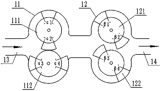
[0038] The method of the present invention can be applied to all types of gear pumps, including internally cut gear pumps and externally cut gear pumps. The present embodiment is an example of externally cut gear pumps, such as figure 1 As shown, it is a structure for eliminating the hydraulic pulse of the circumscribed gear pump, including the gear pump A11 and the gear pump B12 arranged in series, the gear pump A11 and the gear pump B12 are arranged in the same cavity, and one end of the cavity It is connected with the oil supply pipeline A13, and the other end is connected with the working pipeline A14. The gear pump A11 and the gear pump B12 are connected with the driving device, and are driven by the driving device to rotate at constant angular speed. The gear pump A11 includes a rotary piston a 111 and a rotary piston b 112 arranged in cooperation, and the gear pump B12 includes a rotary piston c 121 and a rotary piston d 122, and each of the rotary pistons a-rotary pisto...

Embodiment 2

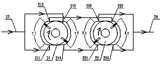
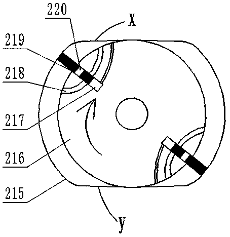
[0044] Such as figure 2 As shown, it is an embodiment of a vane pump designed using the method of the present invention. Taking two pump bodies in series as an example, the vane pump liquid supply system of this embodiment specifically includes a vane pump A21 and a vane pump B22. The vane pump Both A21 and vane pump B22 include a stator and a rotating rotor. The stator includes two sections of arcs whose profiles are positive arcs. The two sections of positive arcs are located within the pump oil angle range. The liquid angles are γ1 and γ2, and the pumping liquid angle of the vane pump B22 is that the sum of the sum of the angles of γ1, γ2, δ1, and δ2 is at least 360°; and the transition curve connecting the two ends of the positive arc is located at In the non-pumping angle range, the transition curve is in tangential contact with the rotor. The rotor is connected with a driving device, and the driving device drives the rotor to rotate at a constant angular velocity.

[...

Embodiment 3

[0051] Such as Figure 5 As shown, the plunger pump is an implementation mode when the technical solution of the present invention is applied. In this embodiment, two single plunger pumps are connected in series as an example for description.

[0052] The plunger pump liquid supply system of this embodiment includes two single plunger pumps in series, plunger pump A31 and plunger pump B32, said plunger pump A31 includes hydraulic cylinder a311 and hydraulic cylinder b312, said hydraulic cylinder A311 and the piston rod of hydraulic cylinder b312 are rigidly connected by connecting piece a313, such as Figure 6 As shown, the connecting piece a313 is a C-shaped piece, and the two outer surfaces are respectively connected with the piston rods of the hydraulic cylinder a311 and the hydraulic cylinder b312, and the two inner surfaces of the connecting piece are in tangential contact with the cam a 314, so that The piston rod moves horizontally with the rotation of the cam. Since the...


PUM


Abstract

The invention discloses a design method capable of eliminating hydraulic pulsation and a device capable of eliminating hydraulic pulsation. The technical scheme of the invention is that a plurality ofsingle hydraulic pumps are connected in series to form a hydraulic pump system to alternate pump fluid, when the single hydraulic pumps act in the respective pump fluid angles, the instantaneous flowrates are kept equal; and the pump fluid angles of all the single hydraulic pumps in the hydraulic pump system add up to at least 360 degrees by setting the angles of the hydraulic pumps. A structural example of applying the method to different types of hydraulic pumps is disclosed, by means of a method alternating pump fluid by the hydraulic pumps connected in series, and the equal instantaneousflow rates of the single hydraulic pumps connected in series, it is ensure that the hydraulic pump system can continuously output hydraulic oil with stable pressure, avoid the problems of system lifereduction, high noise, high cost and unstable rotational speed caused by hydraulic impulse, provide new ideas and schemes to solve the hydraulic impulse problem in the industry, and promote the development of industry technology.

Description

technical field [0001] The invention belongs to the field of hydraulic pumps, and in particular relates to a design method and device capable of eliminating hydraulic pulsation. Background technique [0002] At present, no matter whether the hydraulic pump is a gear pump, a plunger pump or a vane pump, there are defects such as hydraulic pulsation due to the unstable change of the pump oil volume, and the hydraulic pulsation can reduce the life of the system and increase the noise due to vibration. ; When used on a processing machine tool, it will affect the processing accuracy and reduce the reliability due to the unstable speed. The commonly used solution at present is to add additional devices, such as assembling a pressure reducing valve, so that the hydraulic pump can passively reduce the hydraulic pulsation. Although the hydraulic pulsation can be reduced to a certain extent, it cannot solve the problem of hydraulic pulsation from the root cause, and will lead to cost ...

Claims


Application Information

Patent Timeline
IPC IPC(8): F04C11/00F04C2/18F04C2/344F04B23/06F04B9/04F04B1/02F04B11/00
CPCF04B1/02F04B9/042F04B11/00F04B23/06F04C2/18F04C2/3446F04C11/001
Inventor 姚长水
Owner 启东精马液压有限公司
Why Eureka
Try Eureka