Composite steel pipe processing mechanism, structurally reinforced drainage pipe processed by this mechanism

A technology of processing mechanism and composite steel pipe, which is applied in the field of steel pipe processing, can solve the problems of the need to improve the area of ​​the site, large investment in equipment, etc., and achieve the effect of achieving high integration, improving efficiency, and improving uniformity

Active Publication Date: 2019-07-16
GUANGDONG NO 2 HYDROPOWER ENGINEERING COMPANY LTD
View PDF8 Cites 0 Cited by
  • Summary
  • Abstract
  • Description
  • Claims
  • Application Information

AI Technical Summary

Problems solved by technology

However, in the prior art, the cooperation between various sections is mostly manual operation, and different production lines are independent of each other, resulting in a large investment in equipment, and the area occupied by the site needs to be improved.

Method used


Image

  • Composite steel pipe processing mechanism, structurally reinforced drainage pipe processed by this mechanism
  • Composite steel pipe processing mechanism, structurally reinforced drainage pipe processed by this mechanism
  • Composite steel pipe processing mechanism, structurally reinforced drainage pipe processed by this mechanism

Examples


Embodiment 1

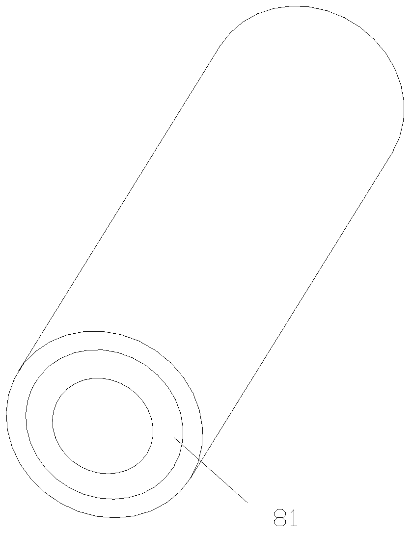
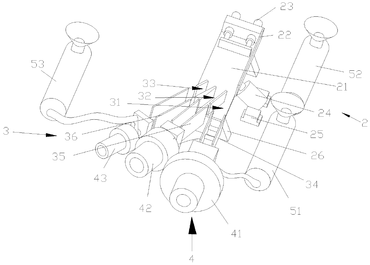
[0040] Such as figure 2 As shown, this embodiment discloses a processing mechanism for a composite steel pipe, including an alignment push-out device 2, a multi-directional conduit device 3, a die head 4, an extruder 5, and a cutting and blanking water-cooling integrated device. The alignment pushing device 2 is used to align the multiple steel billet tubes 81 fed therein and push the aligned steel billet tubes 81 into the multidirectional conduit device 3 . The multidirectional conduit device 3 is used to adjust the conveying direction of multiple billet tubes 81 and ensure that the conveying direction of each billet pipe 81 is different. The die head 4, the extruder 5 correspond one-to-one to the steel billet tube 81 that is branched out from the multi-directional conduit device 3 . The outer surface of the billet tube 81 conveyed from the die head 4 is attached with a layer of resin material extruded from the corresponding extruder 5 . The cutting and blanking water-cool...

Embodiment 2

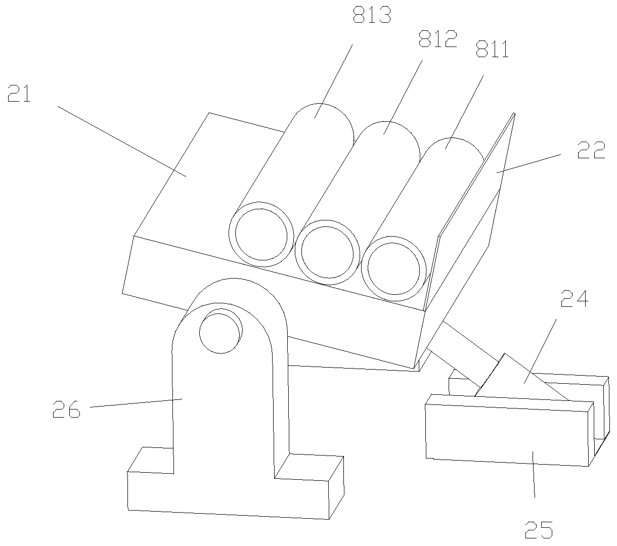
[0044] Such as Figure 2-4 As shown, the difference between this embodiment and the above-mentioned embodiments is that the alignment push-out device 2 includes an alignment push-out workbench 21 , an alignment baffle 22 , and an alignment push-out mechanism 23 . Align and release the workbench 21 from the front to the back direction for its guidance. The alignment push-out mechanism 23 is located at the front end of the alignment push-out workbench 21, and the direction of the motion trajectory of its telescopic end is parallel to the guiding direction of the workbench. Alignment baffle plate 22 is installed on the front section or the front section to the middle section of its right side of alignment ejection workbench 21, or alignment baffle plate 22 extends to alignment ejection workbench 21 its right side from the front end of alignment ejection workbench 21 its right side. side rear end.

[0045] The multi-directional conduit device 3 includes a plurality of guide plat...

Embodiment 3

[0050] Such as Figure 5-8 As shown, the difference between this embodiment and the above embodiments is that the die head 4 includes a die head body 401, and the center of the die head body 401 is connected front and back to form an inlet tube coating cavity. The front section of the inlet pipe coating cavity includes an outer feed cavity layer 4011, a solid barrier layer 4012, and a billet tube inlet cavity layer 4013 from outside to inside. The connection between the outer feeding cavity layer 4011 and the rear section of the inlet pipe coating cavity forms an inwardly protruding stepped structure, the front end of the outer feeding cavity layer 4011 is sealed, and the outer feeding cavity layer 4011 A plurality of outer layer feed through holes 4017 are opened on the front end surface of the tube, and the plurality of outer layer feed through holes 4017 are distributed in a ring with the center of the inlet tube coating cavity as the central axis. The extrusion end of the...


PUM


Abstract

The invention discloses a structure-reinforced drainage pipe. The structure-reinforced drainage pipe comprises a steel billet pipe and a resin material layer which is extruded on the outer surface ofthe steel billet pipe. A resin material comprises the following raw materials by weight: 60-85 parts of polypropylene resin, 20-30 parts of polyvinyl chloride resin, 3-8 parts of barium sulfate, 12-17parts of glass fibers, 11-17 parts of calcium carbonate and 2-5 parts of titanium dioxide. The steel billet pipe consists of the following components by weight: 2-3 parts of carbon, 4-5 parts of silicon, 15-18 parts of manganese, 12-15 parts of nickel, 0.1-0.4 part of sulfur, 0.3-0.5 part of phosphorus, 0.3-1 part of vanadium and 70-90 parts of iron. The invention further discloses a composite steel pipe processing mechanism. The structure-reinforced drainage pipe disclosed by the invention has the advantages of high strength and large binding strength.

Description

technical field [0001] The invention relates to the technical field of steel pipe processing, in particular to a composite steel pipe processing mechanism and a structurally reinforced drainage pipe processed by the mechanism. Background technique [0002] The drain pipes in the prior art mostly adopt two forms of steel pipe or plastic pipe. Wherein, the steel pipe has good strength, but its corrosion resistance needs to be improved; although plastic pipes such as PP pipes, PVC pipes or PE pipes have good corrosion resistance, their strength is insufficient, and broken pipes such as cracking often occur. [0003] In order to improve the strength of plastic pipes, at present, in the market, a variety of raw materials are mixed and extruded to improve the strength, that is, adding reinforcing auxiliary materials to the traditional resin masterbatch to improve the overall strength of the pipe body. Such as the glass fiber reinforced polypropylene plastic disclosed in patent ap...

Claims


Application Information

Patent Timeline
Patent Type & Authority Patents(China)
IPC IPC(8): B29C48/00B29C48/151B29C48/32B29C48/885B29K23/00B29K27/06B29K105/06B29K105/16B29K705/12B29L23/00
CPCB29K2023/12B29K2027/06B29K2105/06B29K2105/16B29K2705/12B29L2023/22
Inventor 谢祥明
Owner GUANGDONG NO 2 HYDROPOWER ENGINEERING COMPANY LTD
Why Eureka
Try Eureka