Novel co-phase detection method and device for segmented telescope
A detection device and telescope technology, applied in the direction of testing optical performance, etc., can solve the problems of low resonance frequency, low co-phase adjustment efficiency, large aperture inertia of a single spliced sub-mirror, etc., and achieve fast piston error adjustment and fast co-phase detection. , the effect of high energy utilization
- Summary
- Abstract
- Description
- Claims
- Application Information
AI Technical Summary
Problems solved by technology
Method used
Image
Examples
Embodiment Construction
[0040] Below in conjunction with the drawings, preferred embodiments of the present invention are given and described in detail.
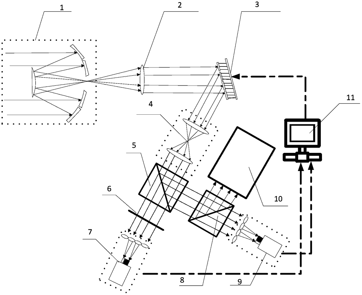
[0041] Such as figure 1 As shown, the present invention is a novel co-phase detection device applied to block-type splicing telescopes, comprising: splicing telescope 1, collimating lens 2, block-type deformable mirror 3, 4f system 4, first beam splitting prism 5, splicing mirror MASK 6, a first Shaker-Hartmann wavefront detector (S-H) 7, a beam splitting prism 8, a second Shaker-Hartmann wavefront detector 9, an imaging system 10 and a control system 11.
[0042] The splicing telescope 1 receives peripheral incident light from the object to be measured, and converges it into outgoing light for emission.
[0043] The collimating lens 2 refracts the outgoing rays into parallel rays or nearly parallel rays.
[0044] The segmented deformable mirror 3 reflects the light beam from the collimating lens 2 to the 4f system 4 .
[0045] The 4f system wil...
PUM
 Abstract
Description
Claims
Application Information
 - R&D
- Intellectual Property
- Life Sciences
- Materials
- Tech Scout
- Unparalleled Data Quality
- Higher Quality Content
- 60% Fewer Hallucinations
Browse by: Latest US Patents, China's latest patents, Technical Efficacy Thesaurus, Application Domain, Technology Topic, Popular Technical Reports.
© 2025 PatSnap. All rights reserved.Legal|Privacy policy|Modern Slavery Act Transparency Statement|Sitemap|About US| Contact US: help@patsnap.com


