
High-speed laser brazing method for automobile ceiling

A canopy and automobile technology, which is applied in welding equipment, metal processing equipment, manufacturing tools, etc., can solve the problems of reducing the connection strength between the automobile canopy and the side walls, turbulent molten pool flow, and increasing equipment costs, so as to suppress the fish scale pattern. And the generation of hump weld bead, reduce the higher requirements of laser output power, reduce the effect of increasing equipment

Active Publication Date: 2018-11-23
GUANGQI HONDA
View PDF3 Cites 5 Cited by
  • Summary
  • Abstract
  • Description
  • Claims
  • Application Information

AI Technical Summary

Problems solved by technology

In the brazing process, the increase of welding speed will cause the flow of the molten pool to be disturbed, resulting in hump weld bead and undercut defects, resulting in the low welding speed of the current car roof, and the welding speed of the car roof is 8mm~70mm / s , cannot meet the production beat of the laser brazing station, hindering the further development of automotive technology
[0004] In the prior art, by changing the structure of the car roof, the distance required for brazing of the car roof is reduced, the brazing time of the car roof is shortened, and the production cycle of the laser brazing station meets the requirements, but this method reduces In addition, by building two laser rooms on the production line, the two laser rooms take turns to process so that the production cycle of the laser brazing station can meet the requirements, but the two laser rooms increase significantly. reduce the cost of equipment, therefore, the above-mentioned prior art is not conducive to large-scale promotion
[0005] In the existing car roof brazing technology, due to the defects of the technical idea itself, the car roof brazing technology cannot be solved fundamentally, and the brazing efficiency of the car roof and the ease of popularization of the technology have not been taken into account.
[0006] The existence of this technical problem hinders the further development of the existing technology

Method used


Image

  • High-speed laser brazing method for automobile ceiling
  • High-speed laser brazing method for automobile ceiling
  • High-speed laser brazing method for automobile ceiling

Examples


Embodiment 1

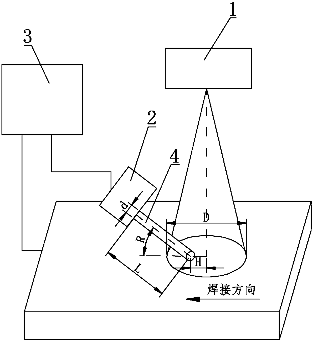
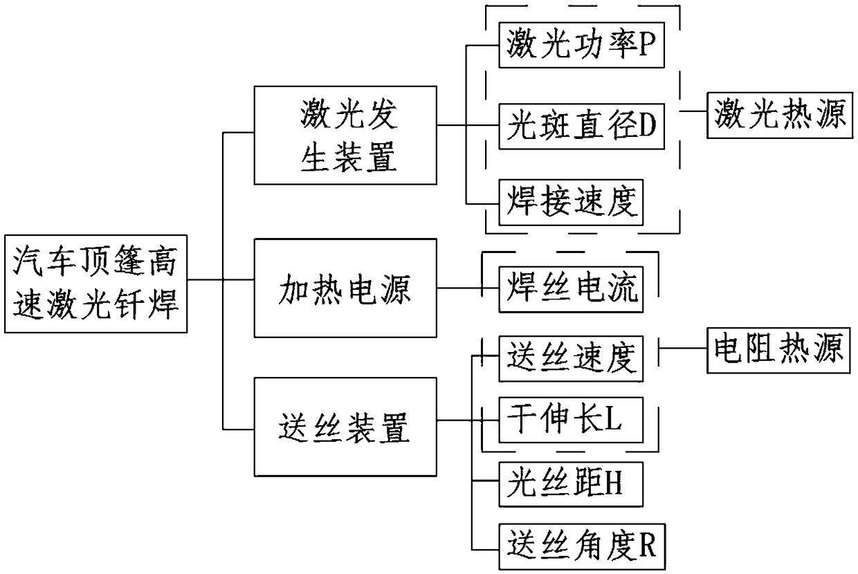
[0035] This embodiment includes a laser generating device 1 , a wire feeding device 2 and a heating power supply 3 for electrical connection with the car roof, and the heating power supply 3 for welding wire 4 is electrically connected to the wire feeding device 2 .

[0036] refer to Figure 1 ~ Figure 4 , the present embodiment provides a method for high-speed laser brazing of an automobile roof, comprising the following steps:

[0037] Step 1: making the welding wire 4 and the car roof electrically connected to the heating power supply, focusing the laser beam generated by the laser generating device 1 on the weld seam of the car roof, and forming a laser spot on the weld seam;

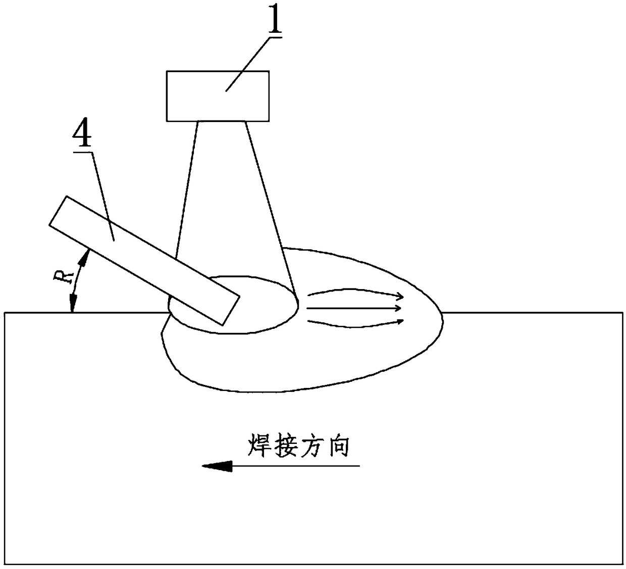
[0038] Step 2: Send the welding wire 4 into the laser spot through the wire feeding device 2. At the same time, the welding wire 4 is in contact with the roof of the car. The contact position of the pool is at the leading edge of the molten pool;

[0039] Step 3: Make the laser spot generated by t...

Embodiment 2

[0054] The difference between this embodiment and the embodiment is that in step 1, the output power P of the laser generator 1 is 4.6-5.9KW, the ratio of the diameter D of the laser spot to the diameter d of the welding wire 4 is D:d=1.5:1, the welding wire The angle formed by the axis of 4 and the moving direction of the welding wire 4 is R=30°, and the ratio of the length L of the welding wire 4 protruding from the wire feeding device 2 to the diameter d of the welding wire 4 is L:d=6:1;

Embodiment 3

[0056] The difference between this embodiment and the embodiment is that in step 1, the output power P of the laser generator 1 is 6KW, and the ratio of the diameter D of the laser spot to the diameter d of the welding wire 4 is D: d=1.7:1, the ratio of the diameter d of the welding wire 4 The angle between the axis and the moving direction of the welding wire 4 is R=25°, and the ratio of the length L of the welding wire 4 protruding from the wire feeding device 2 to the diameter d of the welding wire 4 is L:d=7:1;


PUM


Abstract

The invention relates to the technical field of automobile brazing, in particular to a high-speed laser brazing method for an automobile ceiling. The method includes the following steps that a weldingwire and the automobile ceiling are both electrically connected with a heating power source, laser beams generated by a laser generating device are focused onto a welding line of the automobile ceiling, and laser spots are formed on the welding line; the welding wire is fed into the laser spots through a wire feeding device, and meanwhile the welding wire makes contact with the automobile ceiling; the welding wire is molten under the joint effects of laser energy and resistance heat, a molten pond is formed, and the position, making contact with the molten pond, of the welding wire is locatedon the front edge of the molten pond; and the laser spots generated by the laser generating device and the wire feeding device drive the welding wire to move and perform welding along the trajectorywhere the welding line is located. The high-speed laser brazing method for the automobile ceiling inhibits generating of hump weld passes and figures of fish scale in the brazing process, and achievesthat the brazing speed of the automobile ceiling reaches 100-120 mm / s.

Description

technical field [0001] The invention relates to the technical field of automobile brazing, in particular to a method for high-speed laser brazing of an automobile roof. Background technique [0002] Laser welding technology has been more and more widely used in automobile manufacturing due to its advantages of fast welding speed, low heat input, small welding deformation, and beautiful weld shape. Mainstream technology, most European and American mainstream car manufacturers use laser brazing to connect the roof and side panels of the car. [0003] The welding speed of laser brazing is a key factor affecting the production cycle of the canopy laser brazing station. In the brazing process, the increase of welding speed will cause the flow of the molten pool to be disturbed, resulting in hump weld bead and undercut defects, resulting in the low welding speed of the current car roof, and the welding speed of the car roof is 8mm-70mm / s , cannot meet the production beat of the ...

Claims


Application Information

Patent Timeline
IPC IPC(8): B23K1/005
CPCB23K1/0008B23K1/0056
Inventor 郑世卿庄树祥刘仲洋曾志铭刘祝托黄英俊王跃超
Owner GUANGQI HONDA
Learn More