Method for gob side entry retaining in top-cutting pressure relief roadway in U-shaped steel support roadway

A technology of roof cutting, pressure relief, and roadway retention, which is applied in tunnels, tunnel linings, and earthwork drilling and mining, and can solve problems such as the difficulty of using active support with anchor nets, lack of U-shaped steel support, and broken surrounding rocks. Achieve good social and economic benefits, low cost, and convenient construction

Inactive Publication Date: 2018-11-23
HENAN POLYTECHNIC UNIV
View PDF7 Cites 14 Cited by
  • Summary
  • Abstract
  • Description
  • Claims
  • Application Information

AI Technical Summary

Problems solved by technology

However, in the mining roadway arranged along the floor, when the strength of the coal seam is low, or when a fault or geological structure is encountered, the surrounding rock is relatively broken, and the active support of the anchor net cable is difficult to use. In order to facilitate the roadway support, the roadway usually uses U-shaped steel brackets for passive support. Therefore, there is a lower-strength top-coal or pseudo-roof rock formation above the roadway
At present, for mining roadways with rectangular or trapezoidal cross-sections, there are corresponding gob-side entry retention methods, but there is a lack of methods for using U-shaped steel brackets to support gob-side entry retention in mining roadways

Method used


Image

  • Method for gob side entry retaining in top-cutting pressure relief roadway in U-shaped steel support roadway
  • Method for gob side entry retaining in top-cutting pressure relief roadway in U-shaped steel support roadway
  • Method for gob side entry retaining in top-cutting pressure relief roadway in U-shaped steel support roadway

Examples


Embodiment 1

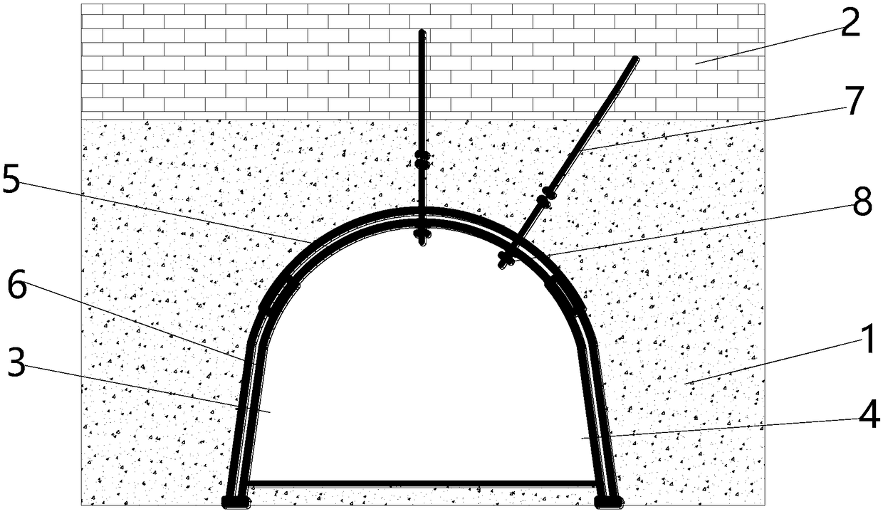
[0036] Step 1) The final structure is: coal seam 1 and the U-shaped steel shed roof beam 5 arranged longitudinally through the interior of the lower half of the U-shaped steel shed roof beam 5. The upper end of the U-shaped steel roof beam 5 is horizontally provided with a roof 2, and the U-shaped steel roof beam and shed legs 6 on the left and right sides are respectively provided with the upper side of the roadway 3 and the lower side of the roadway 4, and the upper end of the U-shaped steel roof beam 5 is uniformly provided with a number of 1 and the anchor cable 7 of the roof 2;

Embodiment 2

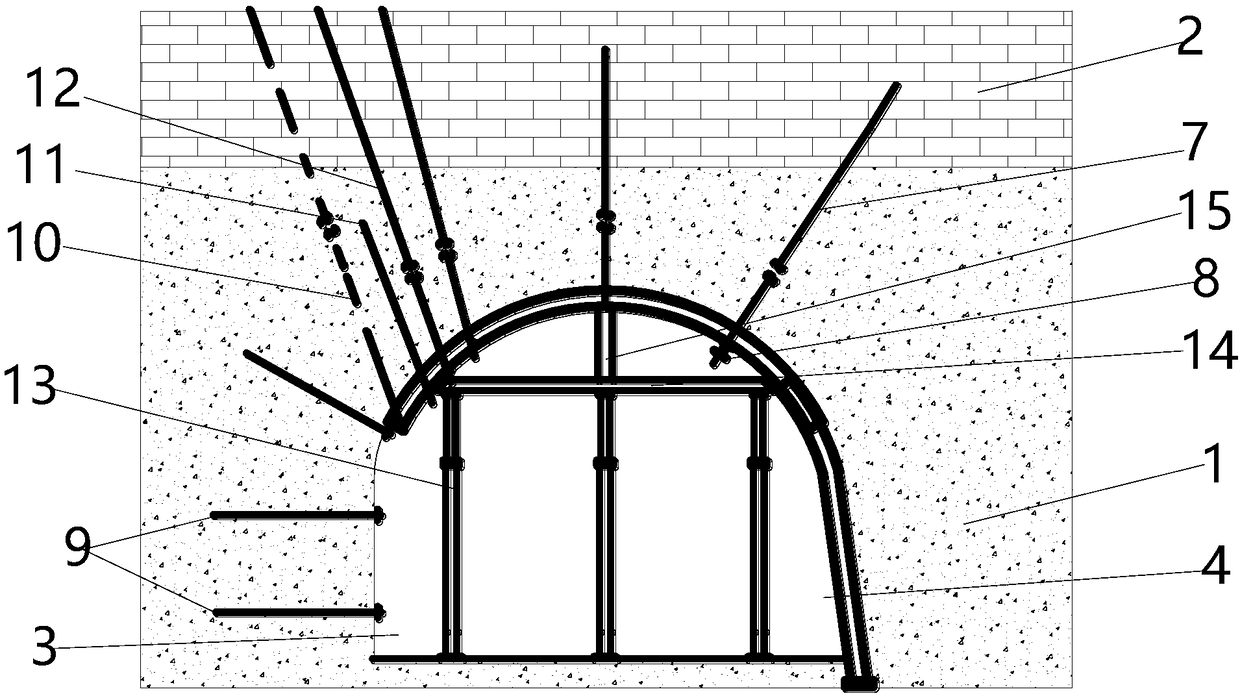
[0038] Step 5) The final structure is: the coal seam 1 and the U-shaped steel shed roof beam 5 arranged longitudinally through the lower half of the interior, the upper end of the coal seam 1 is horizontally provided with a roof 2, and the coal seam 1 on the lower side of the U-shaped steel shed roof beam 5 is about The upper side of the roadway 3 and the lower side of the roadway 4 are respectively arranged, and the upper side of the roadway 3 is horizontally arranged in the coal seam 1 on the left side with a glass fiber reinforced plastic anchor rod 9, and the half section of the U-shaped steel ceiling beam 5 penetrates the coal seam 1 and the roof 2 from the left To the right, there are top-cutting and pressure-relief boreholes 10, equal-strength anchor rods 11, and top-cutting anchor cables 12. The U-shaped steel roof beams 5 on the right side of the top-cutting anchor cables 12 go deep into the coal seam 1 and the roof 2 at equal intervals. A number of anchor cables 7, th...

Embodiment 3

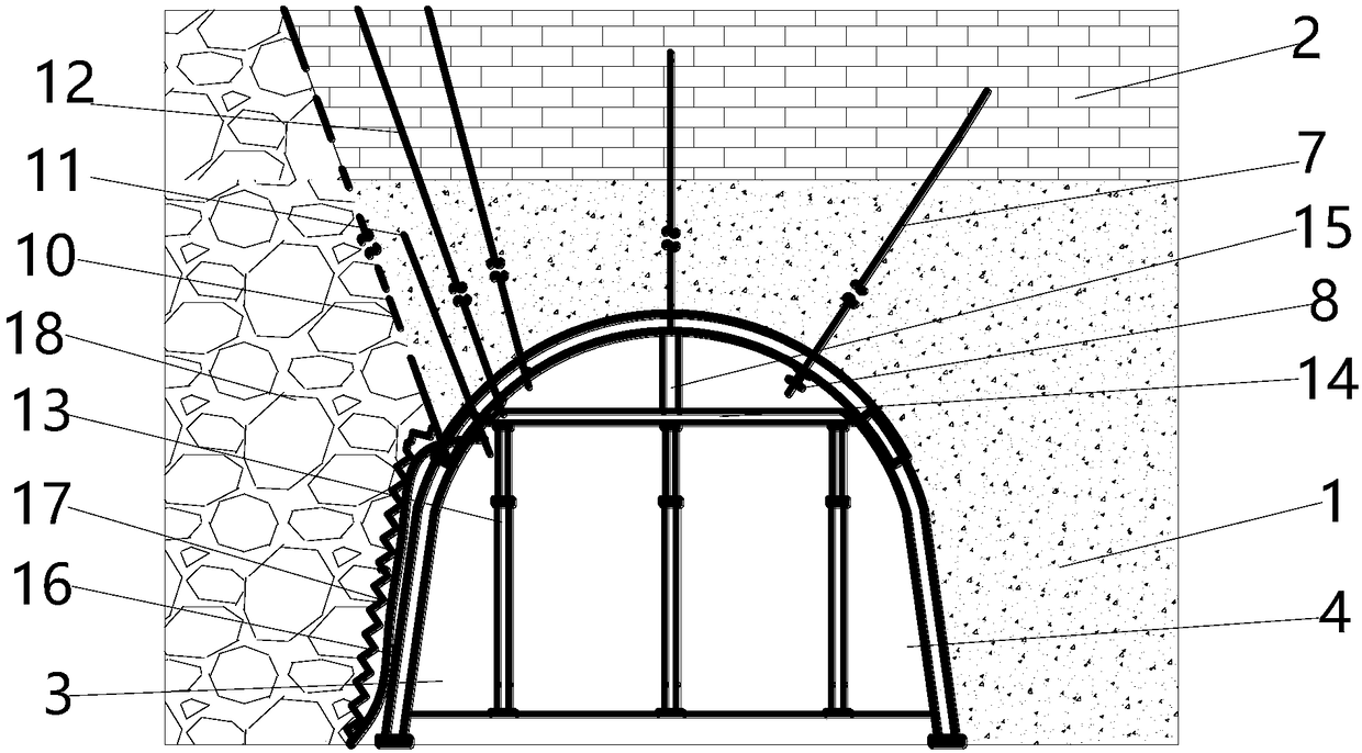
[0040] Step 7) The final structure is: the coal seam 1 and the U-shaped steel shed roof beam 5 installed longitudinally through the lower half of the coal seam 1. The upper side of the roadway 3 and the lower side of the roadway 4 are respectively arranged, and the half section of the U-shaped steel roof beam 5 runs through the coal seam 1 and the roof 2 from left to right. Top-cutting anchor cable 12, goaf 18 is set on the left side of top-cutting pressure relief borehole 10 and roadway upper side 3, and steel wire rope 16 and rhombus net 17 are arranged on the left side of roadway upper side 3, and top-cutting anchor cable 12 The U-shaped steel roof beams 5 on the right side are arranged at equal intervals to go deep into the coal seam 1 and the roof 2, and a number of anchor cables 7 are arranged. The middle position of the lower half of the U-shaped steel roof beams 5 is horizontally provided with π-shaped beams 14, and the π-shaped beams 14 are equidistant and vertically ...


PUM


Abstract

The invention discloses a method for gob side entry retaining in a top-cutting pressure relief roadway in a U-shaped steel support roadway. An arc-shaped backstopping roadway supported by a U-shaped steel frame is adopted for tunneling along the bottom of a thick coal layer with unstable storage, a rock stratum with a stable soft rock stratum or a coal layer is above the arc-shaped backstopping roadway, a joint support technology of 'a U-shaped steel shed, an anchor net cable, an anchor cable joist, a pi-shaped beam and a single hydraulic support column' is adopted, a U-shaped steel shed top beam is reinforced on an advance surface coal wall, dense top-cutting pressure relief drilling and net hanging are conducted, and a top-cutting anchor cable is arranged; shed legs, close to an upper band, of the U-shaped steel shed are removed, an anchor rod is arranged to close the band, and operations such as advance support and the like are conducted on the roadway through the joint support technology. The method has the advantages of low cost and convenient construction, greatly improves the stability of the U-shaped steel support roadway, has high safety, effectively solves the problem that the gob side entry retaining is conducted in the U-shaped steel support arched roadway, and has good social and economic benefits.

Description

technical field [0001] The invention relates to the technical field of roadway support, in particular to a method for retaining a roadway along the gob in a U-shaped steel supported roadway for roof cutting and pressure relief. Background technique [0002] As a coal mining technology, gob-side entry retention can improve roadway maintenance, reduce roadway excavation, ease excavation replacement, and achieve safe production in high-gas working faces and efficient production without coal pillars. The preliminary support of the mining roadway is an important part of the success of the entire gob-side retaining roadway. Under normal circumstances, the mining roadway is excavated along the roof or along the floor, and its cross-sectional shape is rectangular or trapezoidal. However, in the mining roadway arranged along the floor, when the strength of the coal seam is low, or when a fault or geological structure is encountered, the surrounding rock is relatively broken, and the...

Claims


Application Information

Patent Timeline
Patent Type & Authority Applications(China)
IPC IPC(8): E21D11/18E21D20/00
CPCE21D11/18E21D20/00
Inventor 张盛王小良焦振国王龙飞胡跃敏刘建康赵龙刚刘宇鹏王千红闫淑雯
Owner HENAN POLYTECHNIC UNIV
Why Eureka
Try Eureka