Fin material for heat exchanger, and heat exchanger

A technology of heat exchangers and fins, which is applied in the field of heat exchangers, can solve problems such as fin material cracks and large mold wear, and achieve the effects of preventing the reduction of formability and excellent hydrophilicity

Inactive Publication Date: 2018-11-23
FURUKAWA SKY ALUMINUM CORP
View PDF10 Cites 0 Cited by
  • Summary
  • Abstract
  • Description
  • Claims
  • Application Information

AI Technical Summary

Problems solved by technology

In addition, in the aluminum fin material using the hydrophilic colored film of Patent Document 3, since the film contains an inorganic material with high hardness such as an alkali metal salt of silicic acid and alumina, the aluminum alloy plate is processed into For the fin material, due to the high hardness of the coating film, there may be problems that the mold wears heavily and the fin material is prone to cracks

Method used


Image

  • Fin material for heat exchanger, and heat exchanger
  • Fin material for heat exchanger, and heat exchanger
  • Fin material for heat exchanger, and heat exchanger

Examples


Embodiment 1

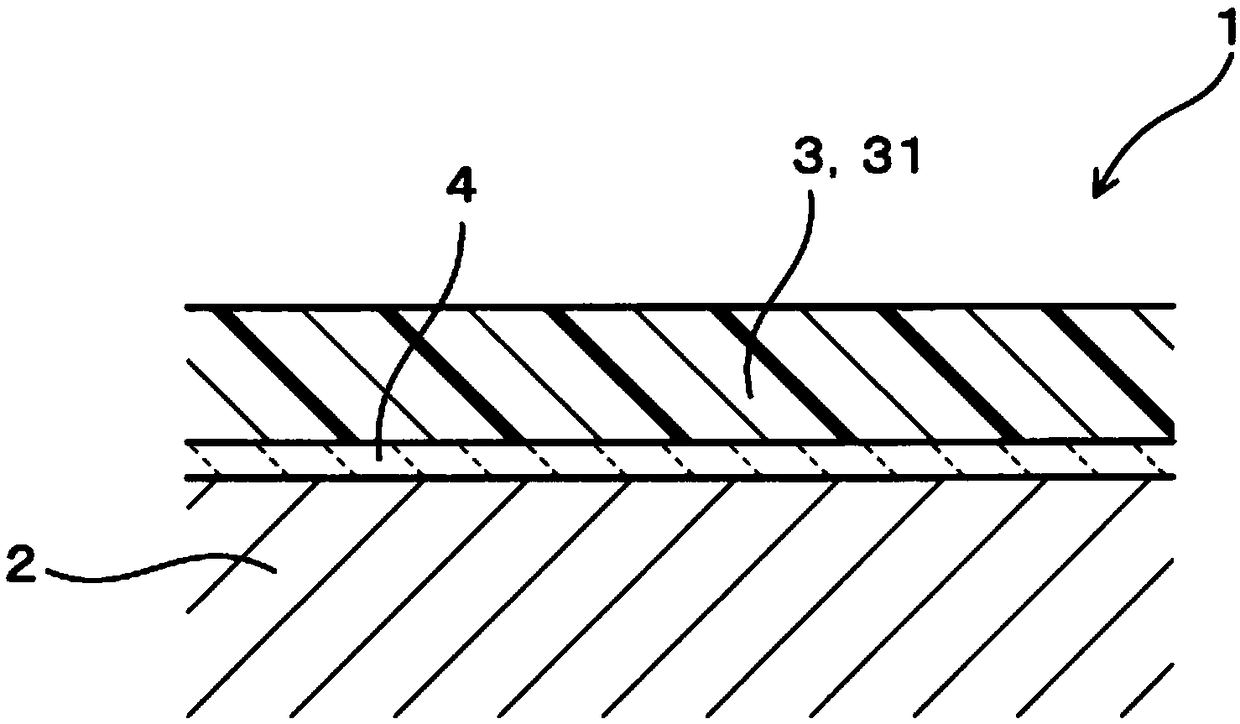
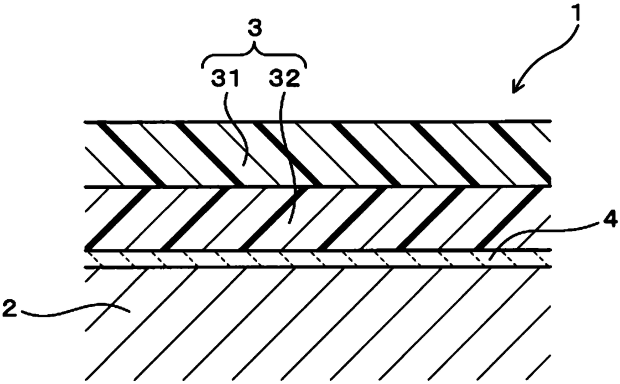
[0061] This example is an example in which fin materials (sample E1 to sample E20) according to examples of the present invention and fin materials (sample R1 to sample R11) according to comparative examples were prepared and these characteristics were evaluated. Such as figure 1 As shown, the fin materials 1 of samples E1 to E20 have a substrate 2 made of aluminum and a coating film 3 formed on the surface thereof. The coating film 3 is composed of a hydrophilic colored film 31 . A chemically synthesized film 4 is formed between the substrate 2 and the coating film 3 . The lamination structure of the film of sample R1 - sample R11 is the same as that of sample E1 - sample E20. Each of the samples E1 to E20, and the samples R1 to R11 differed in the constituent components of the hydrophilic colored film 31 as shown in Table 1 to be described later. The amount of each component in Table 1 is the amount of solid content.

[0062] Hereinafter, the manufacturing method of a fi...

Embodiment 2

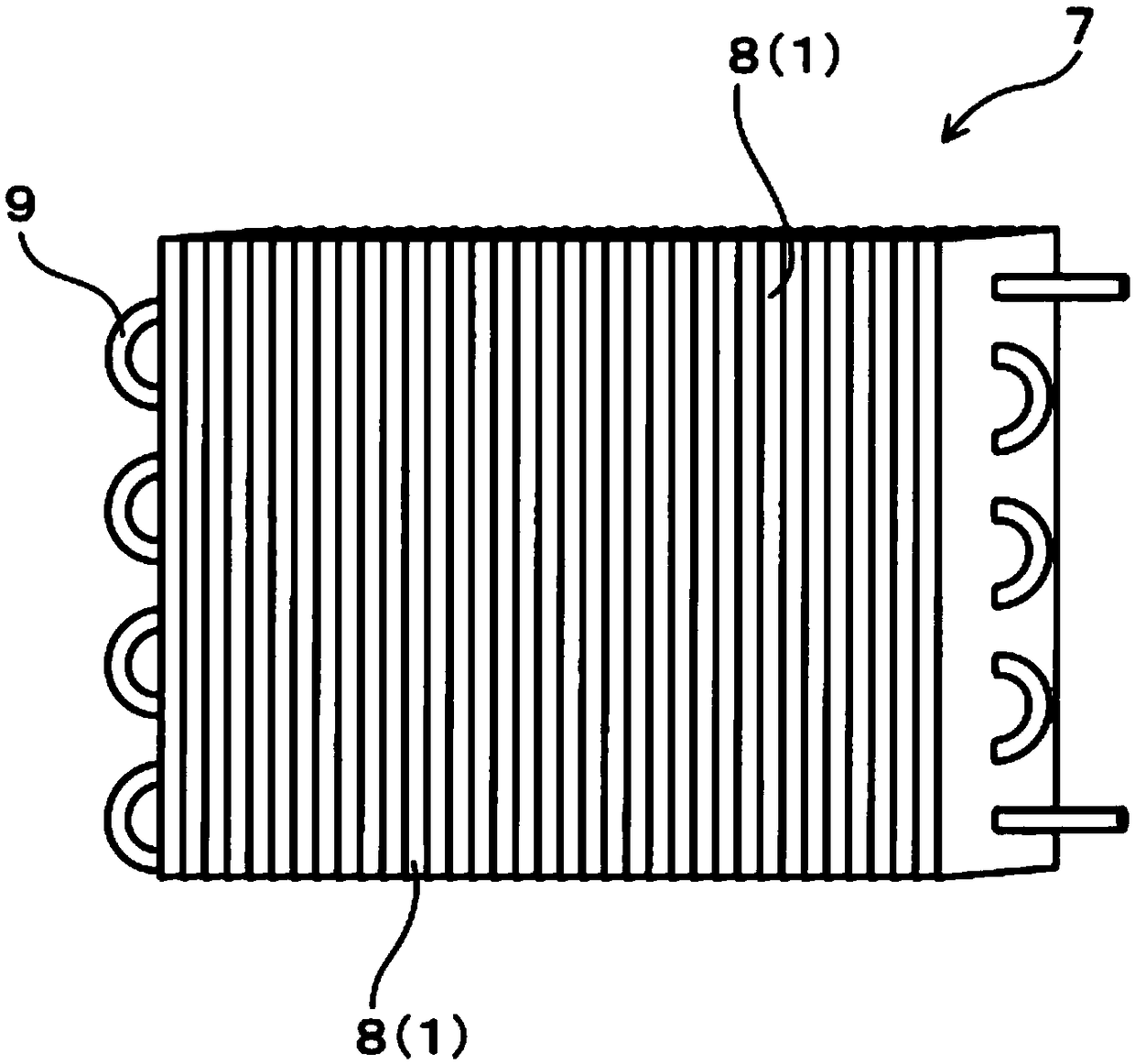
[0101] This example is an example of a heat exchanger including fins made of the fin material of Example 1. Such as image 3 As illustrated, the heat exchanger 7 is a cross-fin tube type, and has a plurality of plate-shaped fins 8 made of a fin material 1 , and a metal tube 9 for heat conduction passing through these fins. The fins 8 are arranged in parallel with predetermined intervals therebetween. The width of the fins 8 is, for example, 25.4 mm, the height is, for example, 290 mm, the stacking pitch of the fins 8 is, for example, 1.4 mm, and the overall width of the heat exchanger 1 is, for example, 300 mm. The height direction of the fins 8 is parallel to the rolling direction of the substrate. The metal tubes 9 in the width direction of the fins 8 are two rows, and the number of metal tubes 9 in the height direction of the fins 8 is 14. In addition, in image 3 Among them, for the convenience of making drawings, the number of metal pipes 9 is omitted. In addition, t...


PUM

PropertyMeasurementUnit
water contact angleaaaaaaaaaa
angleaaaaaaaaaa
heightaaaaaaaaaa

Abstract

Provided are: a fin material for heat exchangers which has a hydrophilic colored coating film that is excellent in terms of hydrophilicity, appearance attractiveness, and resistance to color fading and that has been obtained through one coating step, and which can be prevented from deceasing in formability; and a heat exchanger which includes the fin material. The fin material for heat exchangerscomprises a base (2) constituted of aluminum and, formed thereover, a coating (3) constituted of one or more coating films; and the heat exchanger includes this fin material. The coating (3) comprisesa hydrophilic colored coating film (31) as an outermost surface, the hydrophilic colored coating film (31) comprising an acrylic-modified epoxy resin (A), a melamine resin (B), a perfluoroalkylated alcohol resin (C), and a pigment (D). The content of the pigment (D) in the hydrophilic colored coating film (31) is 1-80 mg/m2. The hydrophilic colored coating film (31) has an angle of contact with water of 20 DEG C or less. After an immersion test in which the fin material for heat exchangers is immersed for 24 hours in running water having a flow rate of 5 L/hr, the degree of dissolution of thehydrophilic colored film in the running water is 1 mass% or less.

Description

technical field [0001] The present invention relates to a fin material for a heat exchanger, and a heat exchanger using the fin material. Background technique [0002] In recent years, heat exchangers for air-conditioning equipment have been designed to make the interval between fins as narrow as possible in order to improve heat exchange efficiency and downsize. Therefore, in the outdoor unit in which the refrigeration equipment is in operation, the condensed water adhering to the surface of the fins tends to exist between the fins in a bridge shape. This increases the ventilation resistance, that is, the resistance value of the airflow passing between the fins, and as a result, the heat exchange efficiency may decrease. [0003] As a solution, the condensed water is formed into a uniform and thin water film by forming a hydrophilic colored film on the surface of the fins, improving drainage, suppressing the increase in ventilation resistance caused by condensed water, and...

Claims


Application Information

Patent Timeline
Patent Type & Authority Applications(China)
IPC IPC(8): F28F1/32F25B39/02F28F13/18
CPCF25B39/02F28F1/32C09D7/65F28F19/04F28F2245/02F28F13/182F28F17/005F28F13/18F25B39/022F28D2021/007F28F1/325
Inventor 世古佳也外山智章上田薰
Owner FURUKAWA SKY ALUMINUM CORP
Why Eureka
Try Eureka