Eureka AIR delivers breakthrough ideas for toughest innovation challenges, trusted by R&D personnel around the world.

Valve mechanical linkage system

A linkage system and mechanical technology, which is applied in the direction of mechanical equipment, multi-way valves, valve devices, etc., can solve the problems of transmission roller surface wear, inconvenient design and manufacture, and high installation and positioning accuracy, so as to avoid the influence of pipeline stress and installation accuracy Easy to meet and compensate for the effect of all-round errors

Pending Publication Date: 2018-11-27
BEIJING AEROSPACE PETROCHEM TECH & EQUIP ENG CORP LTD +1
View PDF4 Cites 2 Cited by
  • Summary
  • Abstract
  • Description
  • Claims
  • Application Information

AI Technical Summary

Problems solved by technology

Since the main and auxiliary valves share a double-slotted linkage, in order to achieve precise control, the traces of the rollers where the two valves are linked must be strictly accurate and their relative deviation from the rotation axis must not be too large. It is very high; and if there is a deviation in the neutrality or position accuracy, it will also affect the transmission, so the installation and positioning accuracy is required to be high; moreover, because the length of the driving force arm and the resistance arm is always changing when the main and auxiliary valves are switched, so The depiction of the slotting trace of the auxiliary valve is very complicated, and its curvature is always changing, which brings great inconvenience to both design and manufacture
[0006] 2) Susceptible to pipeline stress
Because the linkage parts connecting the main and auxiliary valves are integrated, that is, the main and auxiliary valves are rigidly connected, once the valve position changes or the valve body is deformed, the shape and position tolerance between the transmission roller and the groove will be greatly increased, which will directly affect When the transmission accuracy is reached, the transmission roller and the linkage parts are completely disengaged, and the linkage system fails.
[0007] 3) According to the above article, even if the valve is only slightly deformed, it will not cause the transmission instability, but the mating surface between the roller and the linkage will change, which will cause excessive wear on the transmission roller surface, which will affect the transmission. its service life

Method used


Image

  • Valve mechanical linkage system
  • Valve mechanical linkage system
  • Valve mechanical linkage system

Examples


Embodiment Construction

[0040] The technical solution of the present invention will be described in detail below in conjunction with the accompanying drawings and specific embodiments.

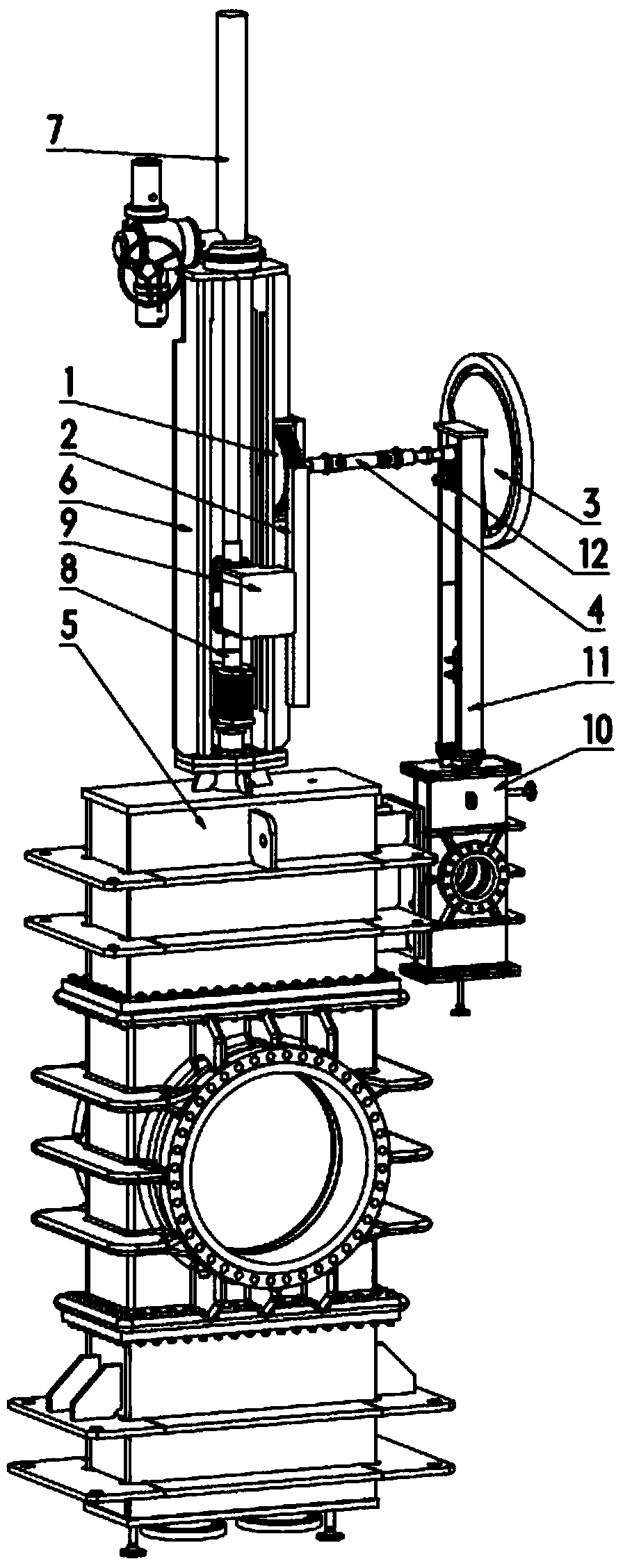
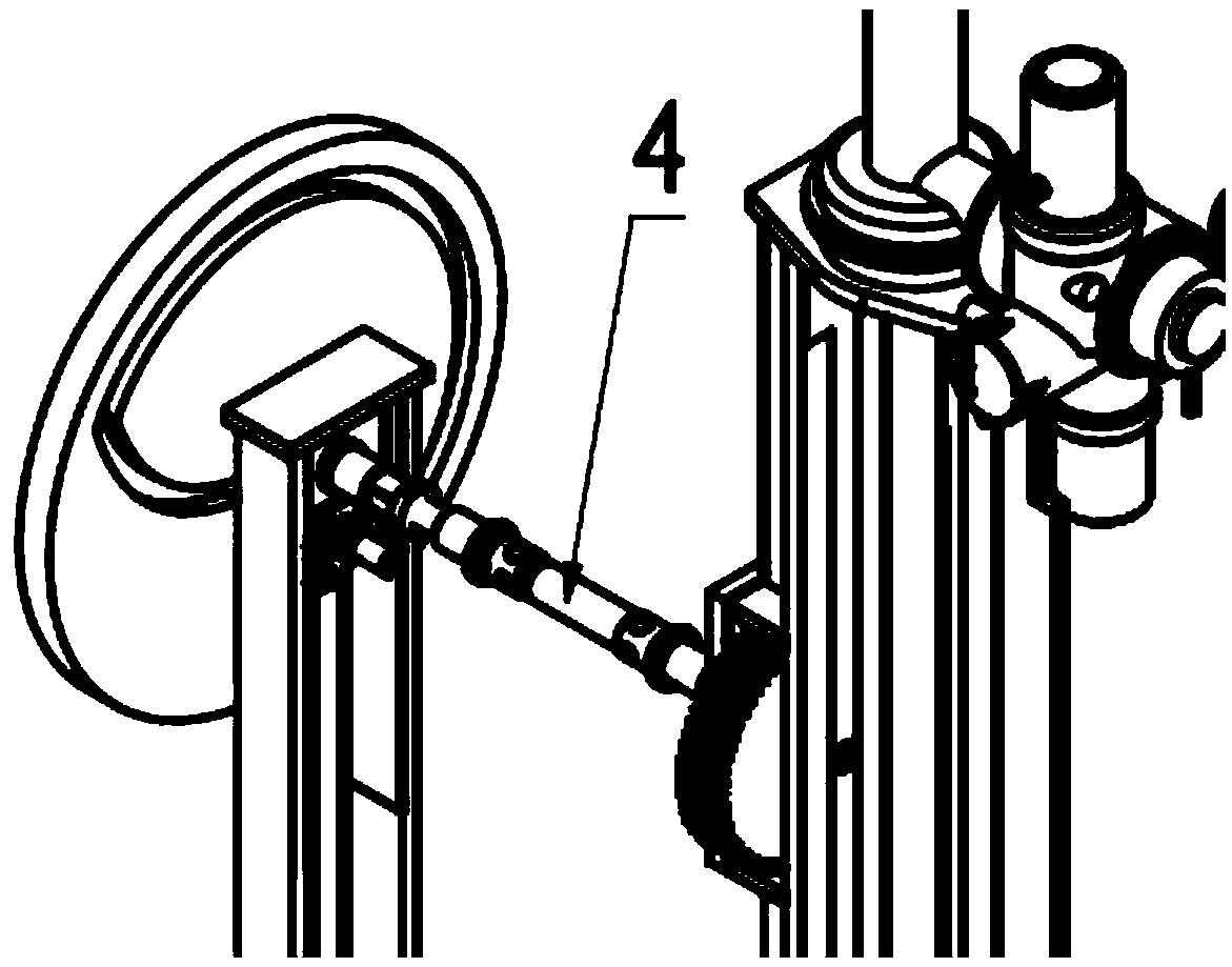
[0041] Such as figure 1 As shown, a valve mechanical linkage system of the present invention includes a gear 1, a rack 2, a cam 3, a flexible coupling 4, a main valve body 5, a main valve bracket 6, a main valve actuator 7, and a main valve movement Component 8, main valve coupling 9, auxiliary valve body 10, auxiliary valve bracket 11, auxiliary valve movement assembly 12;

[0042] 1. Main valve

[0043] The main valve is driven by a rack-and-pinion structure, in which the main valve actuator 7, main valve body 5, and gear 1 are fixedly connected to the main valve bracket 6 respectively;

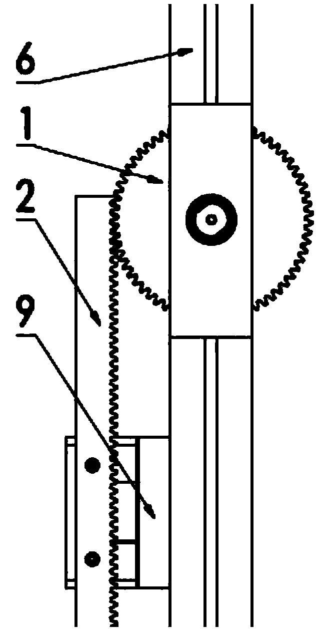
[0044] Such as figure 2 As shown, the gear 1 is a follower in the cooperation of the rack and pinion structure, which is installed on the main valve bracket 6, respectively cooperates with the rack 2 and is fixedly connected w...


PUM


Abstract

The invention belongs to the technical field of mechanical engineering, and in particular relates to a valve mechanical linkage system. The system comprises a gear, a rack, a cam, a flexible coupling,a main valve body, a main valve bracket, a main valve actuator, a main valve movement assembly, a main valve coupling, an auxiliary valve body, an auxiliary valve bracket and an auxiliary valve movement assembly. The system adopts a rack-and-pinion type main valve drive structure, a variable cam type auxiliary valve drive structure and a main and auxiliary valve linkage structure connected by theflexible coupling between a main valve and an auxiliary valve. The main valve and the auxiliary valve are connected by the coupling, and respective mechanisms are fixed on the corresponding valve brackets and are not mutually affected.

Description

technical field [0001] The invention belongs to the technical field of mechanical engineering, and in particular relates to a valve mechanical linkage system. Background technique [0002] In major ethylene plants, ethylene cracking furnace is the key equipment for producing ethylene. Pyrolysis gas valve and coke cleaning valve, as shut-off valves for cracking furnace and coke cleaning pipeline, play an extremely important role, and their performance is related to the production safety of the entire plant. Among them, the cracking valve is used to cut off the cracking furnace and the cracking gas main pipeline, and the coke cleaning valve is used to cut off the cracking furnace and the coke cleaning pipeline. When the cracking furnace switches between the process mode and the coke cleaning mode, if there is no If the actions are performed in the correct order, the pyrolyzate may flow back into the coke cleaning tube and cracking furnace, block the cracking gas pipeline, and...

Claims


Application Information

Patent Timeline
Patent Type & Authority Applications(China)
IPC IPC(8): F16K11/14F16K31/54F16K31/524F16K31/44
CPCF16K11/14F16K31/44F16K31/524F16K31/54C10G9/16F16K3/0254F16K3/029F16K31/52475C10G9/18Y10T137/87732
Inventor 杨帆杨庆朝丁英仁韩静波郭金苏祥刘金贤杨欢李强郭玉生
Owner BEIJING AEROSPACE PETROCHEM TECH & EQUIP ENG CORP LTD
Why Eureka
Eureka Blog
Learn More