
Method for depositing metal electrode

A metal electrode and deposition method technology, applied in circuits, electrical components, laser parts and other directions, can solve the problems of difficult metal stripping, metal curling, photoresist collapse, photoresist deformation, etc. Effect

Active Publication Date: 2018-11-27
HISENSE BROADBAND MULTIMEDIA TECH
View PDF13 Cites 4 Cited by
  • Summary
  • Abstract
  • Description
  • Claims
  • Application Information

AI Technical Summary

Problems solved by technology

However, when electron beam evaporation deposits > 2um metal, when only one deposition rate is used to achieve the target deposition thickness, regardless of the single-layer photoresist structure or the double-layer photoresist structure, under the influence of metal stress and temperature, the thickness will be different to varying degrees. photoresist distortion
For example: when metal is deposited at a low deposition rate, the metal deposition time is too long, the production efficiency is low, and the production cost is too high. The bombardment of the photoresist by high-energy atoms at a high rate will cause the photoresist to collapse, make metal stripping difficult, and cause metal curling problems

Method used


Image

  • Method for depositing metal electrode
  • Method for depositing metal electrode

Examples


Embodiment Construction

[0017] The present invention will be described in detail below in conjunction with specific embodiments shown in the accompanying drawings. However, these embodiments do not limit the present invention, and any structural, method, or functional changes made by those skilled in the art according to these embodiments are included in the protection scope of the present invention.

[0018] The terminology used in the present invention is for the purpose of describing particular embodiments only and is not intended to limit the invention. As used herein and in the appended claims, the singular forms "a", "the", and "the" are intended to include the plural forms as well, unless the context clearly dictates otherwise. It should also be understood that the term "and / or" as used herein refers to and includes any and all possible combinations of one or more of the associated listed items.

[0019] Some embodiments of the present invention will be described in detail below with referenc...


PUM


Abstract

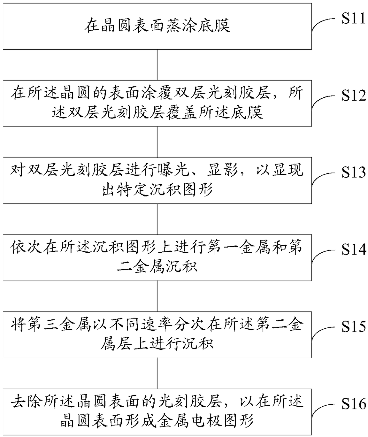
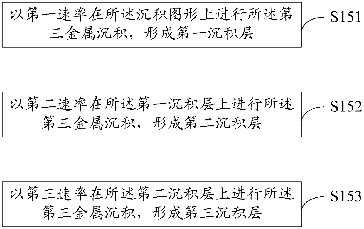
The invention discloses a method for depositing a metal electrode. The method comprises the steps of evaporating a bottom film on the surface of a wafer; coating a double-layer photoresist layer on the surface of the wafer, wherein the double-layer photoresist layer covers the bottom film; and performing exposure and development on the double-layer photoresist layer so as to display a specific deposition pattern; performing first metal deposition and second metal deposition on the deposition pattern in sequence; depositing third metal for multiple times on the second metal layer at different rates; and removing the photoresist layer on the surface of the wafer so as to form a metal electrode pattern on the surface of the wafer. The shape of the photoresist can be well maintained in a modeof matching the deposition with different deposition rates, thereby preventing a problem that the photoresist deforms and collapses under the bombardment of high-energy atoms for a long time, and solving a problem of difficult metal stripping.

Description

technical field [0001] The invention relates to the field of semiconductor optoelectronic technology, in particular to a method for depositing metal electrodes. Background technique [0002] Metal electrode deposition methods are widely used in semiconductor and micro-nano technology, usually there are electron beam evaporation physical deposition methods and electrochemical methods. The electron beam evaporation method has a good vertical incident direction, and better adhesion between the metal and the semiconductor can be obtained, thereby forming a metal circuit on the surface of the laser chip. When making the front electrode (p-electrode) on the surface of the laser chip, it is necessary to perform a yellow light process to expose specific circuit channels, and then use metal deposition to grow gold. [0003] In the metal deposition process with a photoresist mask, a double-layer photoresist is generally used to form a double-layer undercut structure instead of a sing...

Claims


Application Information

Patent Timeline
Patent Type & Authority Applications(China)
IPC IPC(8): H01S5/028H01S5/042
CPCH01S5/028H01S5/0425
Inventor 逯心红郝润豹尚飞
Owner HISENSE BROADBAND MULTIMEDIA TECH
Learn More