
A fuel storage device with high safety performance for new energy

A safety performance and fuel storage technology, which is applied in mechanical equipment, gas treatment/storage purposes, gas treatment/storage effects, etc., can solve problems that affect the personal safety of residents, life threats to drivers, and methane gas leakage, etc., to achieve safe use Convenience, avoiding temperature rise, and preventing leakage

Active Publication Date: 2020-04-03
龙岩市企信工业设计有限公司
View PDF7 Cites 0 Cited by
  • Summary
  • Abstract
  • Description
  • Claims
  • Application Information

AI Technical Summary

Problems solved by technology

[0003] The present invention provides a fuel storage device with high safety performance for new energy, which can effectively solve the problem that when methane is stored in the above-mentioned background technology, most of the tanks are used to store and transport methane gas. There are certain dangers in the process of transportation. If a collision occurs, methane gas will leak, and in severe cases, it will even explode, which will threaten the lives of drivers transporting methane gas. Moreover, when using biogas, natural gas and coal gas During the process, methane gas leakage may also occur, which may lead to poisoning or even death in severe cases. Moreover, when in use, the tank needs to be more than 1.5m away from the open flame, which is inconvenient. If there is a slight methane gas leakage, It will not be noticed by people. It will be too late when methane gas leaks a lot. Moreover, when using it, it is necessary to use a hose to connect the methane outlet. If the connection is not tight, it will cause methane to leak and affect residents. personal safety issues

Method used


Image

  • A fuel storage device with high safety performance for new energy
  • A fuel storage device with high safety performance for new energy
  • A fuel storage device with high safety performance for new energy

Examples


Embodiment

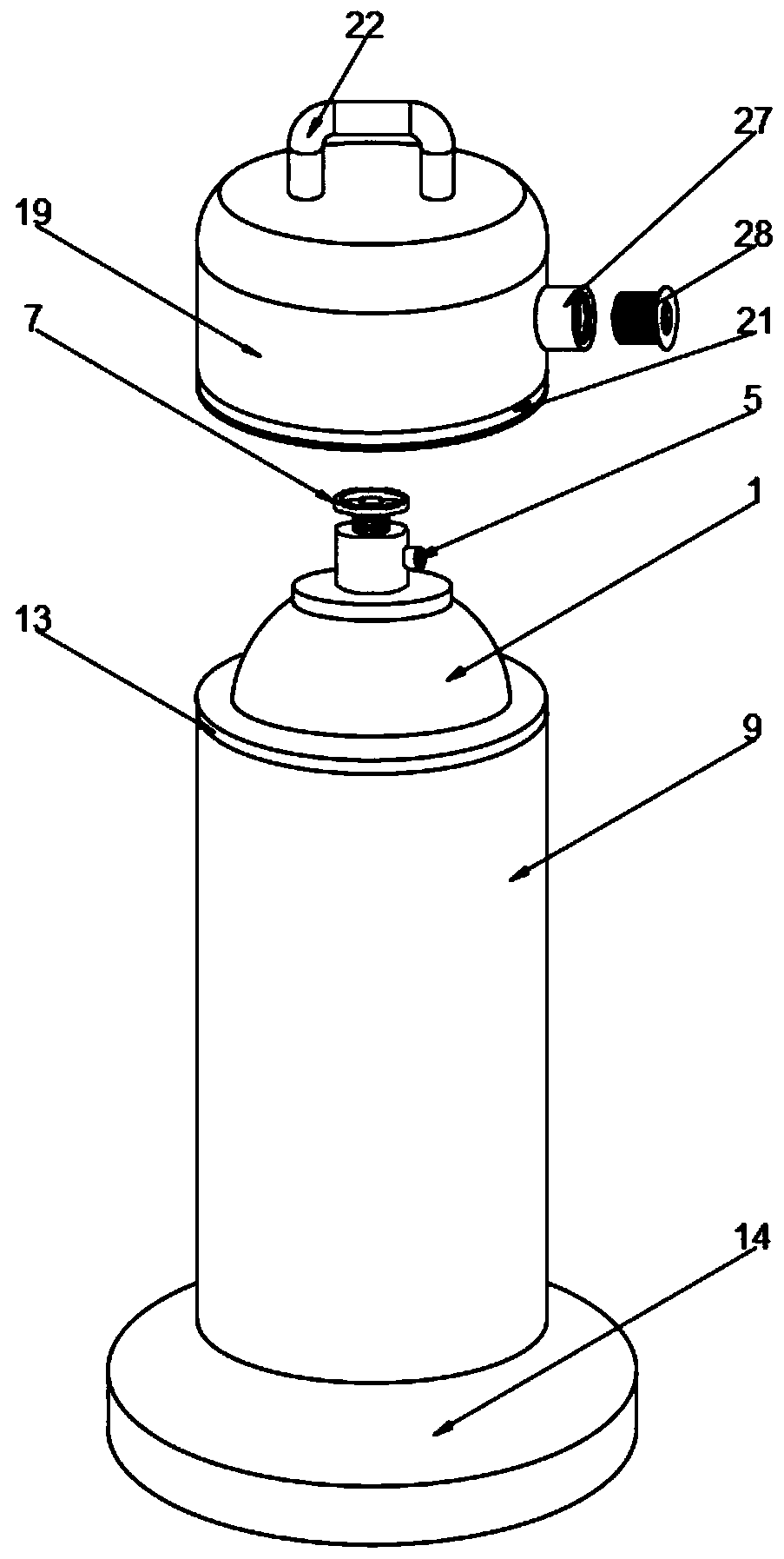
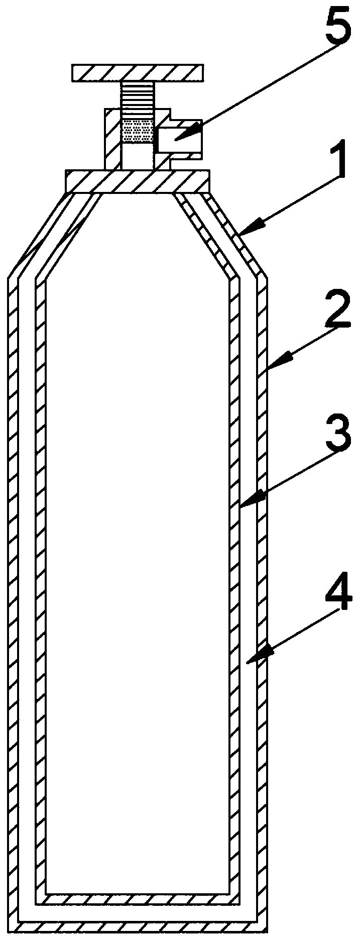
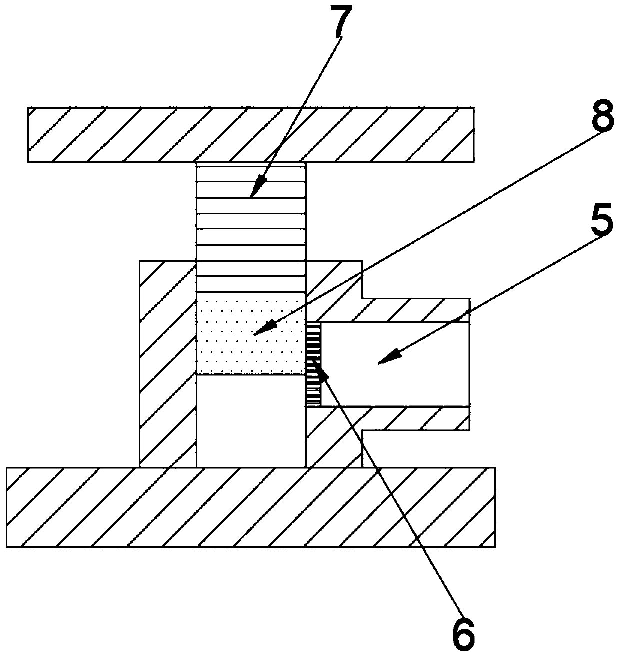
[0033] Example: such as Figure 1-8As shown, the present invention provides a technical solution, a fuel storage device with high safety performance for new energy, including a tank body 1, an outer tank body 2, an inner tank body 3, a leak-proof layer 4, a methane outlet 5, and a screen 6. Valve 7, sealing rubber block 8, protective sleeve 9, first outer shell 10, first inner shell 11, buffer spring 12, first magnet 13, shock-absorbing base 14, shock-absorbing rubber pad 15, shock-absorbing cavity Chamber 16, damping spring 17, damping rubber tube 18, sealing cover 19, sealing rubber ring 20, second magnet 21, handle 22, second outer shell 23, buffer rubber 24, second inner shell 25, methane leakage Alarm 26, connecting port 27, sealing bolt 28, thread 29 and sealing sponge 30, outer tank body 2 is welded on the outside of tank body 1, inner tank body 3 is welded on the inner side of tank body 1, outer tank body 2 and inner tank body 3 There is a leak-proof layer 4 between t...


PUM


Abstract

The invention discloses fuel storage equipment with high safety performance for new energy. The fuel storage equipment comprises a protective cover, a first outer housing, a first inner housing and abuffer spring, wherein the first outer housing is welded at the outer side of the protective cover, and the first inner housing is welded at the inner side of the protective cover; the buffer spring is installed between the first outer housing and the first inner housing. The fuel storage equipment is scientific and reasonable in structure as well as safe and convenient to use; the equipment is provided with the protective cover, the first outer housing, the first inner housing and the buffer spring; tanks collide with each other when being transported due to the jolt of a vehicle, and the collision between the tanks can be buffered by means of the first outer housing, the first inner housing and the buffer spring, so that the collision between the tanks can be reduced; the protective cover is arranged, so that the sunlight exposure to the tanks can be effectively reduced; furthermore, the phenomenon that the pressure of methane gas in the tanks is increased due to temperature rise isavoided; therefore, the safety performance of tank transportation is effectively improved.

Description

technical field [0001] The invention relates to the technical field of new energy storage equipment, in particular to a high-safety fuel storage equipment for new energy. Background technique [0002] New energy generally refers to renewable energy that is developed and utilized on the basis of new technologies, including solar energy, biomass energy, water energy, wind energy, geothermal energy, wave energy, ocean current energy, and tidal energy, as well as the energy between the ocean surface and the deep layer. In addition, there are hydrogen energy, biogas, alcohol, methanol, etc., and coal, oil, natural gas, water energy and other energy sources that have been widely used are called conventional energy sources. With the limitation of conventional energy sources and the increasing environmental problems It is becoming more and more prominent, and the new energy with the characteristics of environmental protection and renewable is getting more and more attention from all...

Claims


Application Information

Patent Timeline
Patent Type & Authority Patents(China)
IPC IPC(8): F17C1/00F17C1/12F17C13/00F17C13/02F17C13/06F17C13/08F17C13/04
CPCF17C1/00F17C1/12F17C13/00F17C13/002F17C13/02F17C13/04F17C13/06F17C13/084F17C2201/0104F17C2201/032F17C2201/056F17C2203/0304F17C2203/0379F17C2203/0629F17C2205/0107F17C2205/0196F17C2205/0311F17C2205/0323F17C2221/033F17C2250/036F17C2260/036F17C2260/038F17C2260/042F17C2265/012F17C2270/0168
Inventor 余娟娟国吉龙
Owner 龙岩市企信工业设计有限公司
Learn More