
Lightning stroke resistant metal unit capable of changing lightning attachment point and preparation method thereof

A metal unit, anti-lightning technology, applied in metal processing, aircraft electrostatic discharger, aircraft lighting protector, etc., can solve the problem of not being able to actively change the lightning entry point and conduction direction, etc., to achieve good practical value and the ability to conduct lightning current Strong, lightweight effect

Pending Publication Date: 2018-12-04
熊秀
View PDF19 Cites 2 Cited by
  • Summary
  • Abstract
  • Description
  • Claims
  • Application Information

AI Technical Summary

Problems solved by technology

[0005] The purpose of the present invention is to provide an anti-lightning metal unit that can change the lightning attachment point, which solves the problem that the existing anti-lightning equipment outside the aircraft cannot actively change the lightning entry point and conduction direction

Method used


Image

  • Lightning stroke resistant metal unit capable of changing lightning attachment point and preparation method thereof
  • Lightning stroke resistant metal unit capable of changing lightning attachment point and preparation method thereof
  • Lightning stroke resistant metal unit capable of changing lightning attachment point and preparation method thereof

Examples


preparation example Construction

[0040] A method for preparing a lightning-resistant metal unit capable of changing the lightning attachment point, comprising the following steps:

[0041] Step 1, open the drawing software, input the design shape, wire diameter, thickness, and gap parameters of the repetitive structure 1 of the anti-lightning strike unit, and create a CAD model of the repetitive structure 1 of the anti-lightning strike unit;

[0042] Step 2, according to the CAD model of the anti-lightning strike unit repeating structure 1 in step 1, select a small punching machine, and input the running track parameters of the punching head at the same time;

[0043] Step 3, take the smooth and flat metal foil and fix it on the flat grinding tool, start the small stamping machine in step 2, make the stamping head move according to the running track parameters, remove the excess part of the metal foil, and keep the anti-lightning unit to repeat the structure 1 metal parts;

[0044] Step 4, repeating steps 3 ...

Embodiment 1

[0047] The anti-lightning strike unit repeating structure 1 is a spiral square shape, the metal foil is copper, and the lightning strike resisting unit repeating structure 1 is 0.2 mm thick. Concrete preparation process is as follows:

[0048] Step 1. Open the drawing software, input the following parameters: the shape is a spiral regular quadrilateral shape with a size of 300mm×300mm, the diameter of the wire is 1mm, and the gap between adjacent rings of wire is 1mm to create a CAD model.

[0049] Step 2. According to the CAD model in step 1, select a small punching machine, and input the running trajectory parameters of the punching head at the same time, and the diameter of the punching head is 0.8mm.

[0050] Step 3. Select a smooth and flat copper foil with a thickness of 0.2mm and a size of 320mm×320mm, fix it on the flat abrasive tool, start the small punching machine, make the punching head move according to the running track parameters, remove the excess part of the m...

Embodiment 2

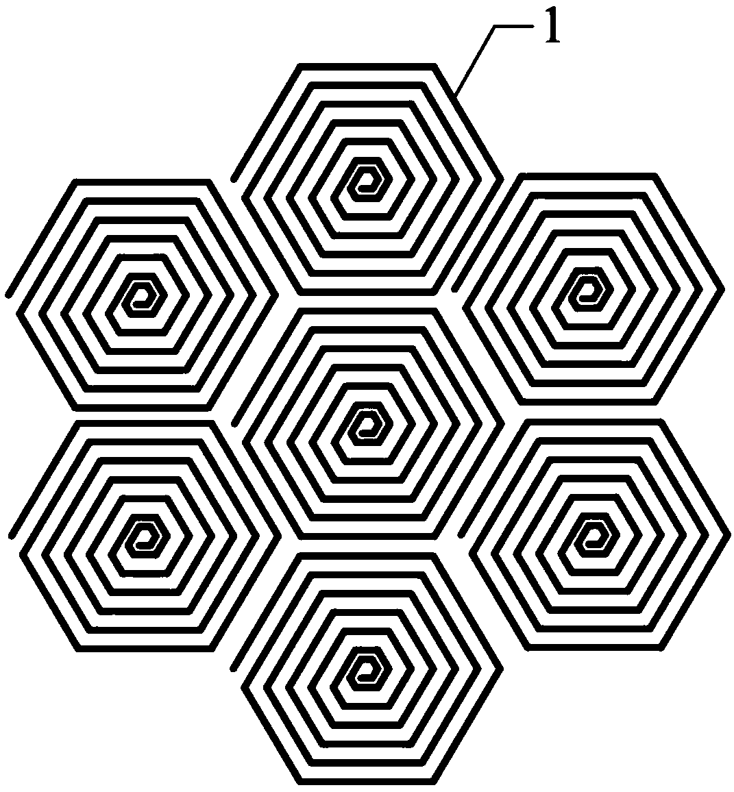
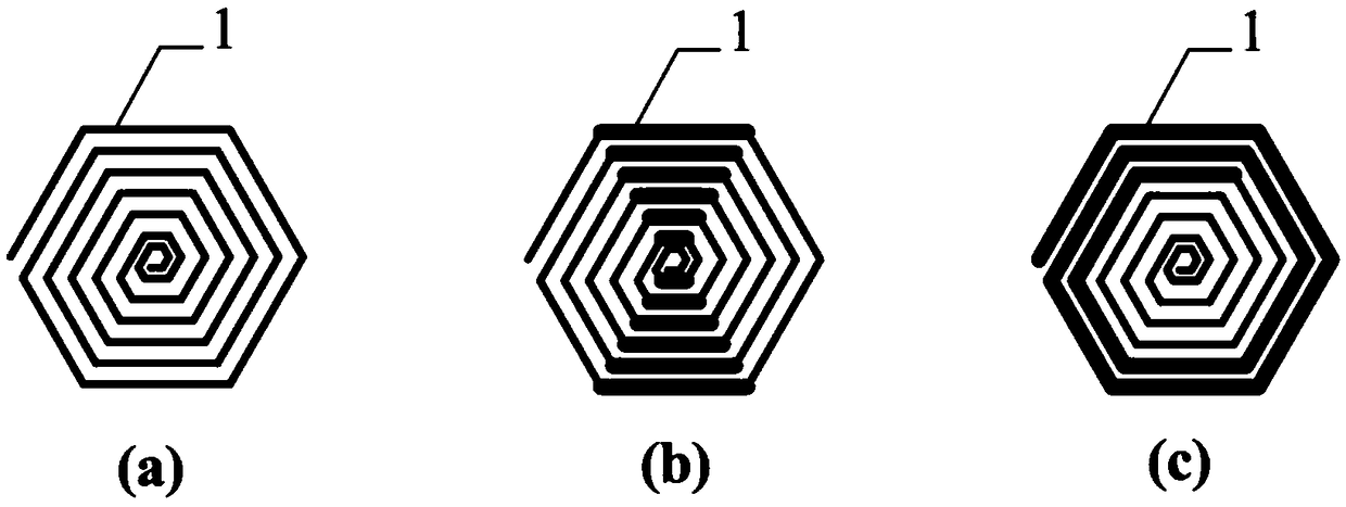
[0054] The anti-lightning strike unit repeating structure 1 is a hexagonal shape, the metal foil is copper, and the lightning strike resisting unit repeating structure 1 has a thickness of 0.1 mm. Concrete preparation process is as follows:

[0055] Step 1. Open the drawing software and input the following parameters: the shape is a hexagonal shape and the side length is 300mm, the wire diameter is 1mm, and the gap between adjacent rings of wire is 3mm to create a CAD model.

[0056] Step 2. According to the CAD model in step 1, select a small punching machine, and input the running trajectory parameters of the punching head at the same time. The diameter of the punching head is 2.8mm.

[0057] Step 3. Select a smooth and flat copper foil with a thickness of 0.1mm and a size of 850mm×850mm, fix it on the flat abrasive tool, start the small punching machine, make the punching head move according to the running track parameters, remove the excess part of the metal foil, and keep...


PUM


Abstract

The invention discloses a lightning stroke resistant metal unit capable of changing a lightning attachment point. The lightning stroke resistant metal unit capable of changing the lightning attachmentpoint comprises a plurality of lightning stroke resistant unit repeating structures which are arranged in sequence in the form of a matrix; the lightning stroke resistant unit repeating structures are in spiral shapes; the lightning stroke resistant unit repeating structures are specifically formed by winding single metal wires; the invention further discloses a preparation method of the lightning stroke resistant metal unit capable of changing the lightning attachment point. The preparation method of the lightning stroke resistant metal unit capable of changing the lightning attachment pointcomprises the steps of preparing CAD models, and then pressing the CAD models into the repeating structures by using a punching machine, and finally, forming the lightning stroke resistant through annealing treatment. The lightning stroke resistant metal unit capable of changing the lightning attachment point has the advantages of simple structure, low cost and convenient use; and the lightning stroke resistant metal unit capable of changing the lightning attachment point can provide a good lightning protection effect for a composite material and finally change the attachment point and the conducting direction of lightning; and by changing the shape, number of turns, wire diameter, distance and so on of the lightning stroke resistant unit, the capacitance and inductance of the lightning stroke resistant can be adjusted so as to control the intensities of a surface induction electric field and a magnetic field and the offset distance of the lightning attachment point.

Description

technical field [0001] The invention belongs to the technical field of lightning protection, and specifically relates to a lightning-resistant metal unit capable of changing the lightning attachment point, and also relates to a preparation method of the lightning-resistant metal unit capable of changing the lightning attachment point. Background technique [0002] Airplanes in the air are vulnerable to lightning strikes. Early airplanes were made of metal materials. Because metal materials have good electrical conductivity, they can effectively receive lightning and conduct lightning current, so lightning will not cause serious damage to the airplane. Since the 1960s, with the rapid development of aerospace and aviation fields, high-performance composite materials have been used more and more widely. Composite materials have low density, light weight, easy molding, and good fatigue resistance. They are applied to aircraft structures. It can reduce the weight of the fuselage...

Claims


Application Information

Patent Timeline
Patent Type & Authority Applications(China)
IPC IPC(8): B64D45/02B26F1/40
CPCB64D45/02B26F1/40
Inventor 范晓宇
Owner 熊秀
Learn More