Railway ballast cleaner

A ballast cleaning machine and railway technology, which is applied in the directions of roads, tracks, ballast layers, etc., can solve the problems such as the inability to guarantee the geometric size of the cross-section of the track bed, the inability to adjust the direction of the vertical rails, and the occupation time, etc., to achieve reliable performance and adaptability. Good performance and the effect of reducing digging resistance

Inactive Publication Date: 2018-12-04
CRCC HIGH TECH EQUIP CORP LTD
View PDF7 Cites 8 Cited by
  • Summary
  • Abstract
  • Description
  • Claims
  • Application Information

AI Technical Summary

Problems solved by technology

However, the screen cleaner does not have a ballast temporary storage system. After the operation is completed, it is necessary to manually backfill the ballast in the excavation pit, which takes up the "skylight" working time; the side-cut blade of the screen cleaner is controlled by a single degree of freedom, and excavates The cutting resistance is large, the efficiency is low, the vertical rail direction cannot be adjusted, the geometric size of the middle track bed section cannot be guaranteed, and the original track bed section is even destroyed.

Method used


Image

  • Railway ballast cleaner
  • Railway ballast cleaner
  • Railway ballast cleaner

Examples


Embodiment 11

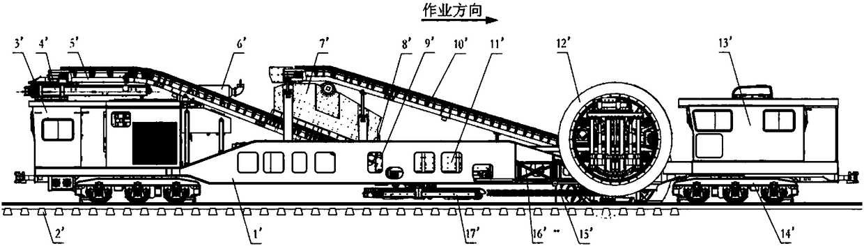
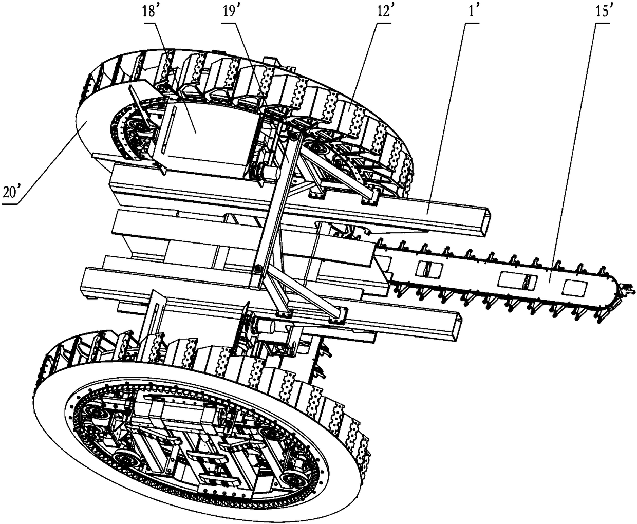
[0052] Embodiment 1.1: a kind of railway track ballast cleaning machine, it comprises vehicle frame 1 ', and this vehicle frame 1 ' is positioned at the front end of working direction and is provided with operator's cab 13 ', and the rear end of vehicle frame 1 ' is provided with running The driver's cab 3', on the frame 1' between the driver's cabs at both ends, there is an excavation bucket wheel 12' arranged from front to back according to the working direction. A screening device 7' is provided at the lower end of the conveyor belt 10', a ballasting device 8' and a main dirt conveyor belt 5' are provided below the screening device 7', a ballasting bucket 9' is provided below the ballasting device 8', The front of the ballasting bucket 9' is provided with a loading and unloading storage and transportation box 11', the lower part of the main dirt conveyor belt 5' is provided with a rotating dirt conveyor belt 4', and the bottom of the ballasting bucket 9' is provided with Ba...

Embodiment 12

[0056] Embodiment 1.2: A railway ballast cleaning machine is the same as Embodiment 1.1, except that the vertical sliding locking device realizes vertical sliding and locking through pneumatic means.

Embodiment 13

[0057] Embodiment 1.3: A railway ballast cleaning machine, the same as Embodiment 1.1, the difference is that the vertical sliding locking device realizes vertical sliding and locking by mechanical means.


PUM


Abstract

A railway ballast cleaner comprises a vehicle frame. Cabs are arranged at the two ends on the vehicle frame. An excavation bucket wheel 12' is further arranged in the position, between the cabs at thetwo ends, of the vehicle frame 1' from front to back in the operation direction. The position behind the excavation bucket wheel 12' is connected with a mixed ballast conveyor belt 10'. A screening device 7' is arranged on the lower portion at the tail end of the mixed ballast conveyor belt 10'. A ballast separation device 8' and a main dirty soil conveyor belt 5' are arranged below the screeningdevice 7'. A ballast falling hopper 9' is arranged below the ballast separation device 8'. A loading and unloading storage and transportation box 11' is arranged in front of the ballast falling hopper 9'. A rotary dirty soil conveyor belt 4' is arranged on the lower portion behind the main dirty soil conveyor belt 5'. A backfill conveyor belt 17' is arranged below the ballast falling hopper 9'. Arail lifting device 16' is arranged in the position, behind the excavation bucket wheel 12', of the vehicle frame. The vehicle frame 1' is further provided with a power transmission system 6', an electrical control system, a hydraulic control system, a brake system, a pneumatic system and a walking system. The excavation bucket wheel 12' comprises a multi-degree-of-freedom lateral cutting type knife board 15'. The multi-degree-of-freedom lateral cutting type knife board can be adjusted at multiple degrees of freedom in the X direction, the Y direction and the Z direction in the use process according to the construction requirements, and the geometric dimension of a ballast bed section can be guaranteed.

Description

technical field [0001] The invention relates to a railway ballast cleaning machine, which belongs to the technical field of railway machinery design and manufacture. Background technique [0002] The ballast cleaning machine is a kind of equipment for cleaning the ballast on the section of the railway track bed or on both sides of the slope. During the cleaning process, the cleaned ballast can be backfilled and the cleaned dirt The soil is dumped to both sides of the line or to the dirt truck through the rotating conveyor belt. [0003] Due to the complex structures of railway turnouts, bridges, and tunnels, it is impossible to use traditional screen cleaners for mechanized cleaning operations. The maintenance work is still mainly manual, with high labor intensity, low efficiency, and poor maintenance quality, which has become a major bottleneck for railway speed-up. . In addition, the side-cut blades in the prior art only have a single degree of freedom. When excavating t...

Claims


Application Information

Patent Timeline
Patent Type & Authority Applications(China)
IPC IPC(8): E01B27/10
CPCE01B27/10E02F5/16E01B27/11
Inventor 张国刚杨斌
Owner CRCC HIGH TECH EQUIP CORP LTD
Why Eureka
Try Eureka