Welding method for reducing site-welding stress deformation of thick-walled steel structure

A welding method and on-site welding technology, applied in the direction of welding/welding/cutting items, welding equipment, welding equipment, etc., can solve the problems of poor fatigue resistance, tediousness, passiveness, etc., and achieve the effect of reducing welding deformation

Active Publication Date: 2018-12-07
HARBIN INST OF TECH +6
View PDF5 Cites 2 Cited by
  • Summary
  • Abstract
  • Description
  • Claims
  • Application Information

AI Technical Summary

Problems solved by technology

[0011] The present invention solves the problems that the existing steel structure butt welding process is passive, cumbersome and difficult to adjust the welding residual strain, and the welding joint structure has poor stability and fatigue resistance, and further provides a method for reducing the on-site welding stress of the thick-walled steel structure. Deformed welding method

Method used


Image

  • Welding method for reducing site-welding stress deformation of thick-walled steel structure
  • Welding method for reducing site-welding stress deformation of thick-walled steel structure
  • Welding method for reducing site-welding stress deformation of thick-walled steel structure

Examples


specific Embodiment approach 1

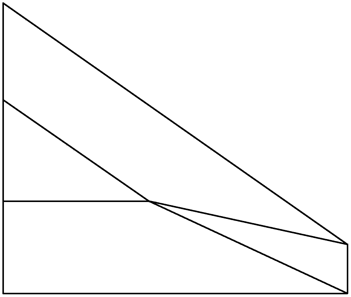
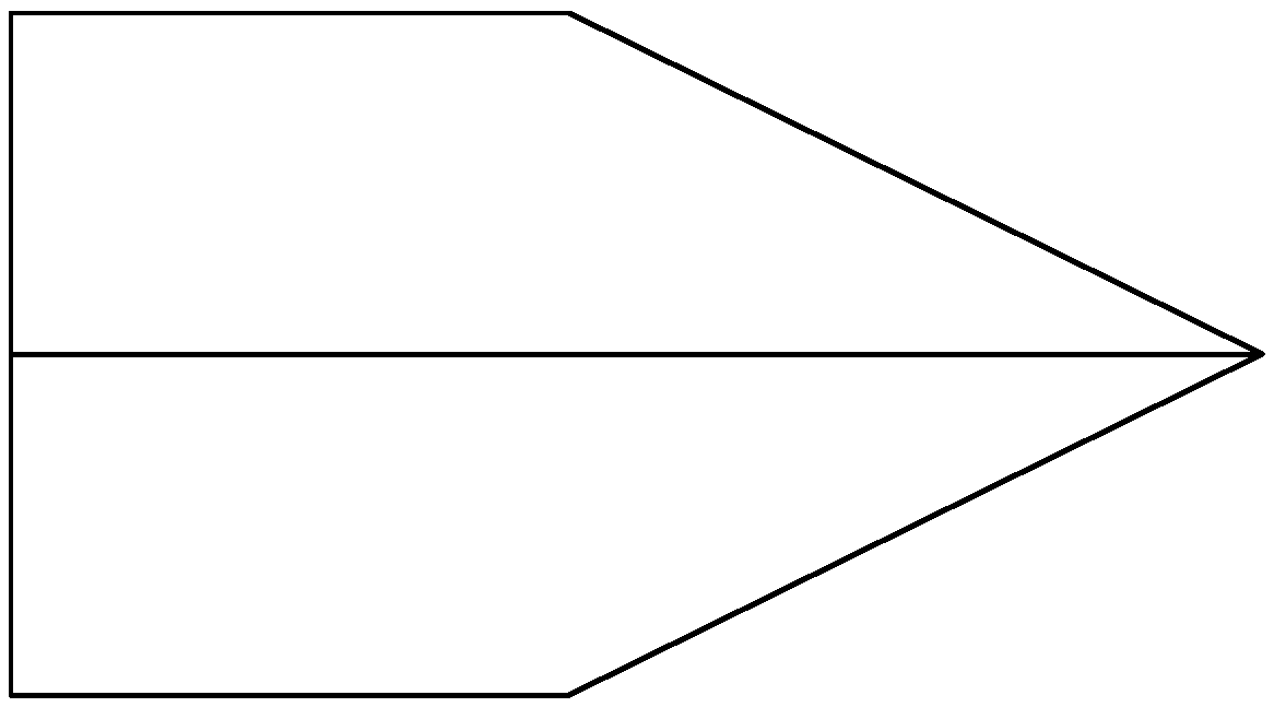
[0038] Specific implementation mode one: as Figure 1~6 As shown, the steps of the welding method for reducing the on-site welding stress and deformation of thick-walled steel structures in this embodiment are as follows:

[0039] Step 1. The material of the built-in web is selected to be the same as that of the base metal of the thick-walled steel structure; the plane geometry and outline size of the built-in web are set to be the same as the cross-section of the welding groove;

[0040] Step 2: At the welding groove of the butt joint, a number of inlaid built-in webs are arranged at intervals along the length direction of the weld, and the "skeleton system structure" is composed of the welding groove wall of the base metal and several inlaid built-in webs ;

[0041] Step 3. For the weld bevel of circular pipe butt joints: arrange the minimum distance between two adjacent built-in webs to be 314mm; for the weld bevel of non-circular pipe butt joints, arrange the minimum dist...

specific Embodiment approach 2

[0045] Embodiment 2: The welding method in step 5 of this embodiment is symmetrical welding, layered welding or segmented welding. In this way, on the basis of the support function of the skeleton formed by the built-in web, the welding stress and the equalization of structural deformation can be better controlled, and the longitudinal welding stress of the weld metal can be reduced as much as possible. Other operation steps are the same as those in the first embodiment.

specific Embodiment approach 3

[0046] Specific implementation mode three: as Figure 1~3 As shown, the profile of the built-in web inlaid in this embodiment is wedge-shaped. According to the specific geometric shape of the welding groove section, the projection of the thickness direction of the built-in web is generally a trapezoid, an equilateral triangle, a scalene triangle or a scalene quadrilateral, etc. Such a design can make the plane geometric shape and size of the built-in web the same as the cross-section of the welding groove, which facilitates the seamless inlay of the built-in web in the welding groove and strengthens the "supporting effect" of the built-in skeleton. Other compositions and connections are the same as those in Embodiment 1 or 2.


PUM

PropertyMeasurementUnit
thicknessaaaaaaaaaa

Abstract

The invention provides a welding method for reducing the site-welding stress deformation of a thick-walled steel structure, and relates to a welding method. The problems that for an existing steel structure, adjustment of welding residual strain to a welding process is passive, cumbersome and difficult, and the structure of welding joints is poor in stability and anti-fatigue performance are solved. The method comprises the steps that multiple inlaid internal webs are arranged at welding grooves of welding groove at intervals in the length direction of a welding seam, wherein a skeleton systemstructure is jointly formed by welding groove walls of base materials and the inlaid internal webs; welding of the internal webs is conducted, wherein back gouging welding is adopted to ensure complete fusion between the internal webs and the base materials of the welding groove walls of the butt joints; and after the skeleton system structure of the butt joints is welded and formed, filling welding is conducted on a partition space formed by the welding groove walls of the base materials and the multiple inlaid internal webs in an enclosing manner, and cover surface welding is conducted in the longitudinal welding direction of the welding seam. The welding method is used for reducing the site-welding stress deformation of the thick-walled steel structure.

Description

technical field [0001] The invention relates to a welding method for reducing on-site welding stress and deformation of a thick-walled steel structure, belonging to the technical field of welded structures. Background technique [0002] The steel structure has the advantages of high strength, good toughness, good seismic performance, and fast construction speed. It is very suitable for the development of modern engineering structures to towering, long-span, and heavy-duty structures, and engineering applications are increasing. In super high-rise buildings, long-span buildings and long-span bridges, heavy-duty industrial plants and special structures, the thickness of steel plates required for main stress components such as beams, columns, supports, shear walls, and trusses is increasing. Even if a combined structure that can give full play to the respective advantages of steel and concrete and significantly reduce the wall thickness of the steel plate is adopted, the thickn...

Claims


Application Information

Patent Timeline
Patent Type & Authority Applications(China)
IPC IPC(8): B23K31/00B23K31/02B23K37/00B23K101/06B23K103/04
CPCB23K31/003B23K31/022B23K37/00
Inventor 方洪渊戴立先陈波刘中华查晓雄鲍爱莲钟彬王玉银苗若愚王湛杜淼刘万辉才维忠马千里钟雪霏周琦张海峰王晓楠黄垒
Owner HARBIN INST OF TECH
Why Eureka
Try Eureka