Heat exchange insulation pipeline structure
A technology for thermal insulation and heat exchange pipes, which is applied to tubular objects, household appliances, and other household appliances. It can solve the problem of waste heat not being effectively used, and achieve the goals of avoiding uneven heat exchange, saving energy, and saving energy. Effect
- Summary
- Abstract
- Description
- Claims
- Application Information
AI Technical Summary
Problems solved by technology
Method used
Image

Examples
Embodiment 1
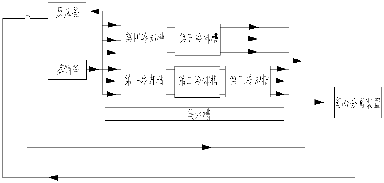
[0043] Such as figure 1 As shown, this embodiment discloses a heat exchange and heat preservation pipeline structure for plastic pipe processing, including waste heat collection and heat preservation pipelines, first cooling heat exchange pipelines, second cooling heat exchange pipelines, waste heat transport heat preservation pipelines, return material heat preservation pipelines, A reaction kettle, a first water-cooled tank assembly, a second water-cooled tank assembly, a centrifugal separation device, and a still.
[0044] The first water-cooling tank assembly includes several first water-cooling tanks, and the second water-cooling tank assembly includes several second water-cooling tanks.
[0045] The feed end of the waste heat collection and heat preservation pipeline is connected with the steam outlet of the distillation kettle, and the discharge end of the waste heat collection and heat preservation pipe is divided into three branches. Wherein, the first branch is resp...
Embodiment 2
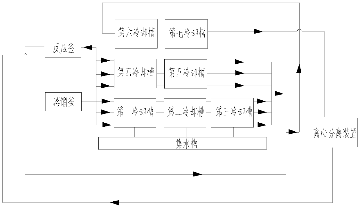
[0061] Such as figure 2 As shown, the difference between this embodiment and the above-mentioned embodiments is that the heat exchange and heat preservation pipeline structure also includes a third cooling heat exchange pipeline, and after the first cooling heat exchange pipeline, the second cooling heat exchange pipeline and the waste heat transport and heat preservation pipeline are connected in parallel, It is connected in series with the third cooling heat exchange pipeline.
[0062] The third cooling heat exchange pipe is arranged in the third water-cooling tank assembly, and the third water-cooling tank assembly includes a plurality of third water-cooling tanks, which are arranged sequentially from front to back according to the cooling sequence. The number of the third cooling heat exchange pipes is multiple and connected in parallel with each other, and each third cooling heat exchange pipe extends from the starting end of the third water cooling tank body at the star...
Embodiment 3
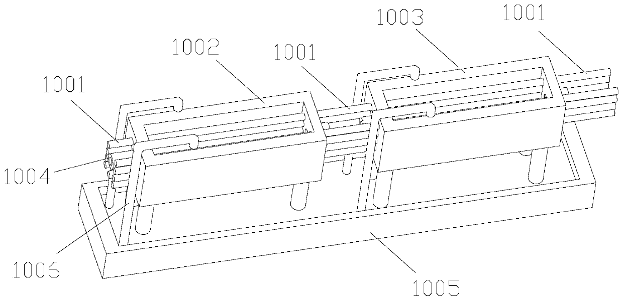
[0065] Such as Figure 3-4 As shown, the difference between this embodiment and the above-mentioned embodiments is that the openings of all the water-cooling tanks in this embodiment are upward, and corresponding cooling and heat exchange devices are provided on the two side inner walls and the bottom wall of each water-cooling tank. pipeline. The front and rear ends of all water-cooling tanks are provided with material guide ports 1004, which are used for pipes to pass through and out of the tanks.
[0066] In some embodiments, a sump 1005 is provided at the bottom of each set of water-cooling tank assemblies, and the sump 1005 communicates with the corresponding water-cooling tank through pipes 1006 or extends above the opening of the corresponding water-cooling tank. In the present invention, the contact between each heat exchange pipe and the corresponding tank body is sealed by a sealing member.
[0067] Because there is a gap between the pipe material and the material ...
PUM
| Property | Measurement | Unit |
|---|---|---|
| Thermal conductivity | aaaaa | aaaaa |
| Thermal conductivity | aaaaa | aaaaa |
| Thermal conductivity | aaaaa | aaaaa |
Abstract
Description
Claims
Application Information
 - R&D
- Intellectual Property
- Life Sciences
- Materials
- Tech Scout
- Unparalleled Data Quality
- Higher Quality Content
- 60% Fewer Hallucinations
Browse by: Latest US Patents, China's latest patents, Technical Efficacy Thesaurus, Application Domain, Technology Topic, Popular Technical Reports.
© 2025 PatSnap. All rights reserved.Legal|Privacy policy|Modern Slavery Act Transparency Statement|Sitemap|About US| Contact US: help@patsnap.com