Centrifugal coating device and coating method for prefabricated insulator

A factory prefabricated and coated device technology, applied in the direction of insulators, electrical components, circuits, etc., can solve the problems of affecting finished products, unreasonable, high maintenance costs, etc., and achieve the effects of improved efficiency, uniform thickness, and improved safety

Inactive Publication Date: 2018-12-11
ELECTRIC POWER RESEARCH INSTITUTE OF STATE GRID SHANDONG ELECTRIC POWER COMPANY +1
View PDF7 Cites 9 Cited by
  • Summary
  • Abstract
  • Description
  • Claims
  • Application Information

AI Technical Summary

Problems solved by technology

Robotic spraying operations have problems such as high equipment purchase and maintenance costs, serious paint waste when spraying large areas, and flammable mist generated during spraying, requiring all electrical equipment in the workshop to take explosion-proof measures
Therefore, whether it is for economic or safety considerations, there are unreasonable places to use robotic spraying.
The manual dip coating operation is easily restricted by various factors such as different technical levels of workers, operation qualification rate, labor cost, physical strength, etc., which will affect the quality and efficiency of the finished product.
And the fluidity of the dip coating must be guaranteed. The solution adopted is to dilute the coating by filling the coating with organic solvents, so as to ensure better fluidity. However, a large amount of organic solvents will inevitably cause them to be emitted into the air. In the process, it causes waste of organic solvents and also seriously pollutes the environment

Method used


Image

  • Centrifugal coating device and coating method for prefabricated insulator
  • Centrifugal coating device and coating method for prefabricated insulator
  • Centrifugal coating device and coating method for prefabricated insulator

Examples


specific Embodiment 1

[0046] Specific Example 1: Centrifugal Coating of Chained Double Umbrella Insulators

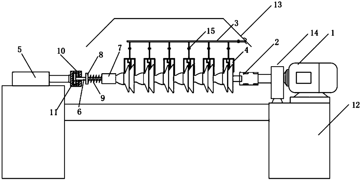
[0047] 1. After the lap joint is completed, the chain-type double-umbrella insulator string is pulled and fixed by the traction device, so that the insulators will not hang down; make the ball-end hanging ring on the tail of the last insulator of the insulator and the bowl head at the end of the coupling 2 The hanging ring is hooked and connected, and the bowl head hanging ring on the head of the first-stage insulator is pulled and fixed by the traction device, which is convenient for hanging after the coating is completed. The motor 1 and the insulator are fixedly connected by a coupling 2, and the coupling 2 has a photoelectric speed sensor for automatic control of the revolution angle. The photoelectric speed sensor is electrically connected with the PLC. The photoelectric speed sensor collects the number of revolutions of the motor, transmits the signal to the PLC, and controls the revo...

specific Embodiment 2

[0052] Specific embodiment 2: column type insulator coating centrifugal coating

[0053] 1. The post insulator does not need to be fixed by tension. The ball-end hanging ring on the tail of the insulator is hooked to the bowl-head hanging ring at the end of the coupling 2, and the other end is suspended in the air. It is connected to the bottom end of the fitting for convenience after coating is completed. hanging. The motor 1 and the insulator are fixedly connected by a shaft coupling.

[0054] 2. The paint is transported to the root of the shed of the insulator through the paint pipeline, and the motor 1 drives the insulator to perform centrifugal motion, thereby realizing spot coating. Through the action of centrifugal force, the upper and lower sides of the insulator are coated at the same time, and finally meet at the edge of the insulator to form a complete overcoating process. And it is evenly coated round by round to form a closed annular recoating process.

[0055]...


PUM


Abstract

The invention belongs to the field of insulator composite anti-pollution flashover coating equipment and method, in particular to a centrifugal coating device and a coating method applied to insulatorcoating. The invention adopts the centrifugal coating method with the rotating coating reagent of the workpiece insulator stationary, the coating thickness is uniform, smooth, free of bubble, bump, hanging flow, concave mark and other defects, and the coating process is convenient to disassemble and assemble. Compared with the traditional way of spraying by manipulator, the safety is greatly improved, and the quality and efficiency of the finished product are significantly improved compared with the artificial dip coating. The device and the coating method of the invention are suitable for coating outer umbrella insulators (single umbrella, double umbrella or multiple umbrellas), column insulators and other insulators.

Description

technical field [0001] The invention belongs to the field of insulator composite anti-pollution flashover coating equipment and methods, and in particular relates to a factory-prefabricated insulator centrifugal coating device and coating method applied to insulator coating. Background technique [0002] At present, in the coating of composite anti-fouling flashover coatings for insulators, it basically relies on manipulator spraying or manual dipping. Robotic spraying operations have problems such as high equipment purchase and maintenance costs, serious paint waste when spraying large areas, and flammable mist generated during spraying, requiring all electrical equipment in the workshop to take explosion-proof measures. Therefore, whether it is for economical or safety considerations, the use of manipulator spraying is unreasonable. The manual dip coating operation is easily restricted by various factors such as different technical levels of workers, operation pass rate, ...

Claims


Application Information

Patent Timeline
Patent Type & Authority Applications(China)
IPC IPC(8): H01B19/04
CPCH01B19/04
Inventor 苏建军宋志强宋利强宋聚强游传榜
Owner ELECTRIC POWER RESEARCH INSTITUTE OF STATE GRID SHANDONG ELECTRIC POWER COMPANY
Why Eureka
Try Eureka