
A high-efficiency battery for a new energy vehicle

A new energy vehicle and battery technology, applied in lead-acid batteries, lead-acid battery electrodes, lead-acid battery construction, etc., can solve the problems of deteriorating battery cycle performance, easy to fall off, and reducing battery charging acceptance, and improve charging acceptance. capacity, improve overall performance, improve the effect of cycle performance

Inactive Publication Date: 2018-12-11
CHINA VOCATIONAL NORTHERN ZHIYANG BEIJING EDUCATION TECH CO LTD
View PDF5 Cites 0 Cited by
  • Summary
  • Abstract
  • Description
  • Claims
  • Application Information

AI Technical Summary

Problems solved by technology

Under such working conditions of traditional lead-acid batteries, coarse lead sulfate crystals that are easy to fall off are easily formed on the surface of the pole, which cannot be transformed into lead during the subsequent charging process, resulting in a decrease in the battery's charge acceptance and worsening the battery cycle. performance

Method used

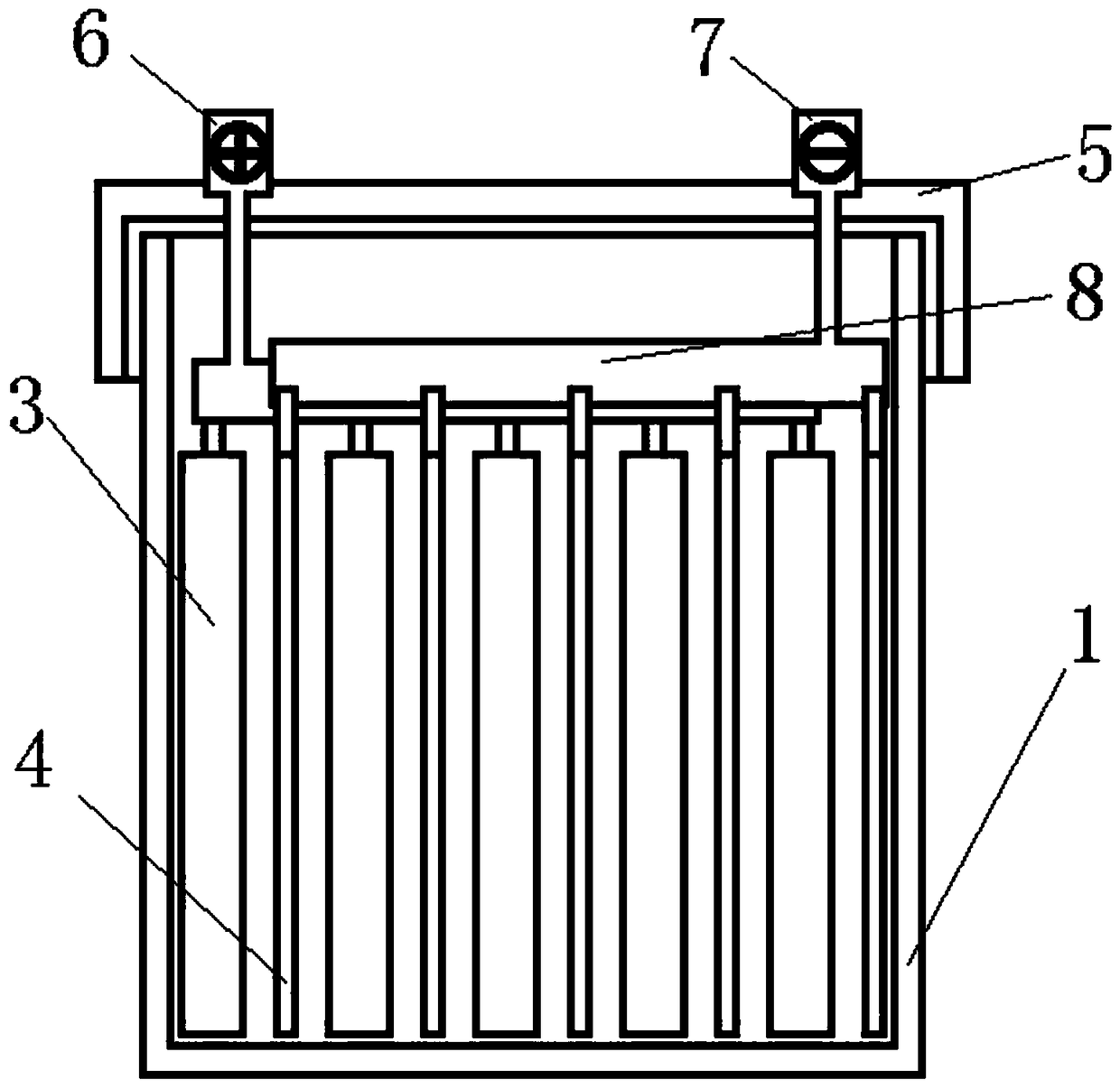
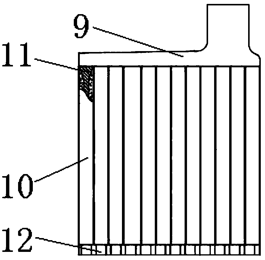
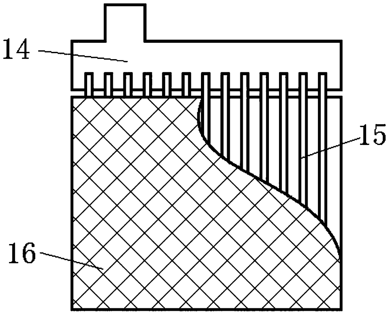

Image

  • A high-efficiency battery for a new energy vehicle
  • A high-efficiency battery for a new energy vehicle
  • A high-efficiency battery for a new energy vehicle

Examples


Embodiment 1

[0045] Such as figure 1 As shown, a tube-type negative plate 4 of a lead-carbon battery of the present invention, the plate includes a lead-calcium multi-element alloy negative plate 4 grids and filled active material powders with a lead-plated surface, and the negative plate 4 grids are beams 14 and The fence structure that the conductive core 15 that is perpendicular to it constitutes, the negative electrode plate 4 grids are provided with non-woven fabric cover layer 16, the gap between cover layer 16 and conductive core 15 is filled with active material, and active material is to contain the following material by weight percentage Composition: 88.41wt% of lead powder, 10wt% of capacitive carbon material, 0.4wt% of carbon black, 0.5wt% of barium sulfate, 0.1wt% of sodium lignosulfonate, 0.5wt% of humic acid and 0.09wt% of short fiber.

[0046] The cross section of the jacket layer 16 is circular.

[0047] The capacitive carbon material is 5wt% of activated carbon, 2wt% of ...

Embodiment 2

[0055] Such as figure 1 Shown, a kind of lead-carbon battery tubular negative pole plate 4 of the present invention, pole plate comprises the carbon foam negative pole plate 4 grids that surface adopts lead-plated treatment and the active material powder that fills, and negative pole plate 4 grids are beam 14 and its perpendicular The fence structure formed by the conductive core 15, the outer surface of the 4 grids of the negative plate is provided with a polyester sheath 16, and the gap between the sheath 16 and the conductive core 15 is filled with an active material, and the active material is composed of the following materials by weight percentage: lead powder 69.25 wt%, capacitive carbon material 25wt%, carbon black 0.5wt%, barium sulfate 2.0wt%, sodium lignosulfonate 1.2wt%, humic acid 2.0wt% and short fiber 0.05wt%.

[0056] The cross section of the jacket layer 16 is oval.

[0057] The capacitive carbon material is 10wt% of activated carbon, 3wt% of expanded graphit...


PUM

PropertyMeasurementUnit
specific surface areaaaaaaaaaaa

Abstract

The invention relates to the field of power batteries, in particular to a high-efficiency battery for a new energy vehicle, comprising a shell, wherein the shell is a rectangular shell structure withan opening facing upward; A electrode plate group comprise a plurality of positive electrode plates and a plurality of negative electrode plate arranged alternately and overlapped to form an electrodeplate group; An end cap that closes the opening of the housing; The electrode comprises positive electrode pillars and negative electrode pillars arranged at both ends of the upper part of the end cap, wherein the positive electrode pillars and the negative electrode pillars pass through the end cap through respective through holes, extend into the shell, and are respectively connected with the corresponding positive electrode plates and the negative electrode plates through an electrical connection plate. The aim of the invention is to stabilize the lead paste by the way of the tubular electrode plate, so that the lead paste is not easy to fall off, the discharge efficiency is guaranteed, and the service life is prolonged.

Description

technical field [0001] The invention relates to the field of power batteries, in particular to a high-efficiency storage battery for new energy vehicles. Background technique [0002] With the continuous development of new energy storage and power markets, higher requirements are placed on the energy density, power density and cycle life of lead-acid batteries. Especially in hybrid vehicles and intermittent new energy storage applications, secondary batteries are required to have good charge acceptance and long cycle life under partial state of charge. Under such working conditions of traditional lead-acid batteries, coarse lead sulfate crystals that are easy to fall off are easily formed on the surface of the pole, which cannot be converted into lead during the subsequent charging process, resulting in a decrease in the battery's charge acceptance and worsening the battery cycle. performance. Contents of the invention [0003] The purpose of the present invention is to ...

Claims


Application Information

Patent Timeline
Patent Type & Authority Applications(China)
IPC IPC(8): H01M4/04H01M4/16H01M4/583H01M10/12H01M10/613H01M10/615H01M10/655H01M10/6554H01M10/658
CPCH01M4/0478H01M4/16H01M4/583H01M10/12H01M10/613H01M10/615H01M10/655H01M10/6554H01M10/658Y02E60/10Y02P70/50
Inventor 曹振峰曹玲玲
Owner CHINA VOCATIONAL NORTHERN ZHIYANG BEIJING EDUCATION TECH CO LTD
Learn More