Magnetic separation device and method for treating oily sludge

A magnetic separation device and sludge technology, applied in sludge treatment, fertilization equipment, biological sludge treatment, etc., can solve the problems of unstable operation, large differences, long cycle, etc., and achieve good degreasing effect and wide application range Wide, easy-to-operate effects

Inactive Publication Date: 2018-12-14
BINZHOU UNIV
View PDF4 Cites 0 Cited by
  • Summary
  • Abstract
  • Description
  • Claims
  • Application Information

AI Technical Summary

Problems solved by technology

[0003] Oily sludge is generally a stable suspoemulsion system composed of oil-in-water (o/w), water-in-oil (w/o) and suspended solids. The dehydration effect is poor, and the sludge composition and physical properties are affected by sewage water quality, treatment process, Influenced by factors such as dosing agents, the differences are large, the treatment is difficult, and the oil content varies greatly. Some of them have the value of recycling and reuse, and the oily sludge contains PAHs, heavy metals and ot

Method used


Image

  • Magnetic separation device and method for treating oily sludge

Examples


Example Embodiment

[0028] Example 1

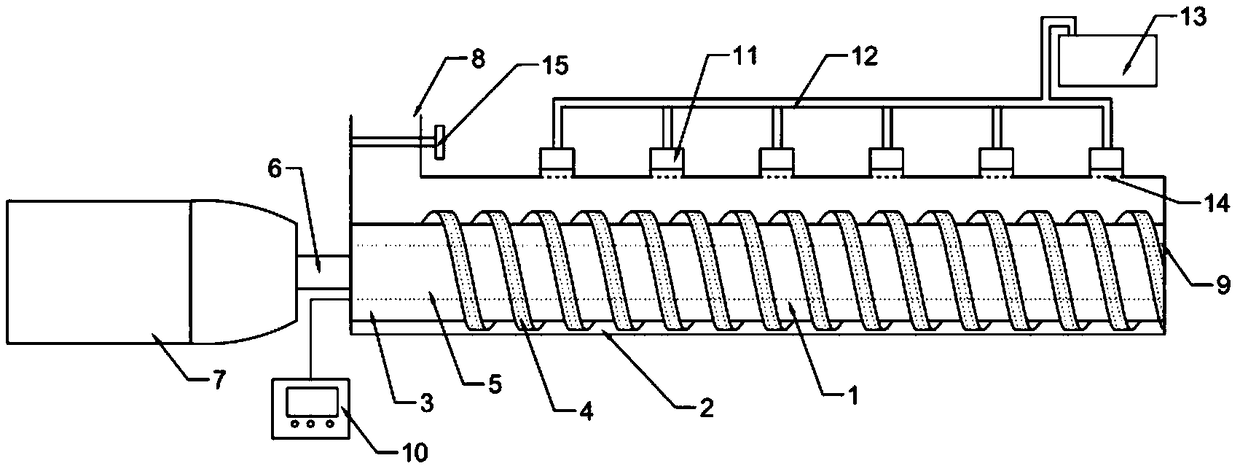
[0029] A magnetic separation device, comprising a magnetic roller 1 and a housing 2 outside the magnetic roller 1, the magnetic roller 1 includes a cylindrical rotating shaft 3 and a helical fin 4 surrounding the rotating shaft 3, the rotating shaft 3 and the helical fin 4 An electromagnet 5 is provided inside, and the electromagnet 5 is connected with a power supply (not shown in the figure), and the rotating shaft 3 is connected to the motor 7 outside the housing 2 through the transmission rod 6; A sludge inlet 8 is provided, and a sludge outlet 9 is provided at one end away from the motor 7 . The thickness of the spiral fin 4 is 3cm. The magnetic roller 1 is 2 cm away from the lower shell 2 and 8 cm away from the upper shell 2 . The magnetic roller 1 is at a certain distance from the casing 2, which is beneficial to the throwing and mixing of the sludge in the casing under the action of the rotation of the magnetic roller, which is beneficial to improvi...

Example Embodiment

[0032] Example 2

[0033] A method of treating oily sludge, comprising:

[0034] (1) The pH value of the oily sludge to be treated is adjusted to 11.5;

[0035] (2) Add Fe to the oily sludge obtained in step (1) 3 o 4 , and stir evenly;

[0036] (3) The oily sludge obtained in step (2) is processed with the magnetic separation device described in Example 1;

[0037] (4) The sludge discharged from the magnetic separation device is sent to the filter press for dehydration;

[0038] (5) Ferment the dehydrated sludge to make organic fertilizer.

[0039] The oily sludge with a water content of 88% and an oil content of 10% was treated according to the above steps. The control group was directly dehydrated by a filter press, and the water content, oil content, etc. of the treated sludge were measured respectively. The data are as follows :

[0040] Table 1 Comparison of treatment effects

[0041]

[0042] From the above experimental results, it can be seen that the...


PUM


Abstract

The invention relates to a sludge treatment method and device, and particularly relates to a magnetic separation device and a method for treating oily sludge. The magnetic separation device comprisesa magnetic roller and a shell outside the magnetic roller; the magnetic roller comprises a cylindrical rotating shaft and spiral fins surrounding the rotating shaft; an electromagnet is arranged inside the rotating shaft and the spiral fins; the electromagnet is connected with a power supply; the rotating shaft is connected with a motor outside the shell through a transmission rod; one side, closeto the motor, of the shell is provided with a sludge inlet; and one side, away from the motor, of the shell is provided with a sludge outlet. The method for treating the oily sludge comprises the following steps: adjusting the pH value of the oily sludge to be treated to 10-12; adding a magnetizing agent, and uniformly carrying out stirring; carrying out treatment by using the magnetic separationdevice; sending discharged sludge to a filter press for dewatering; and then, carrying out fermentation to prepare an organic fertilizer. According to the invention, cutting, uniform mixing and grease adsorption are carried out continuously in a process of conveying the sludge, and the oil removal effect is good.

Description

technical field [0001] The invention relates to a sludge treatment method and device, in particular to a magnetic separation device and a method for treating oily sludge. Background technique [0002] The sludge produced by the sewage treatment system of petrochemical enterprises mainly comes from the bottom sludge of the grease trap, the scum of the flotation tank, and the remaining activated sludge, which are collectively referred to as "three sludges". Oily sludge also includes oily sludge polluted in iron and steel smelting, oily sludge polluted by heavy oil in ship repairing and shipbuilding yards, etc. [0003] Oily sludge is generally a stable suspoemulsion system composed of oil-in-water (o / w), water-in-oil (w / o) and suspended solids. The dehydration effect is poor, and the sludge composition and physical properties are affected by sewage water quality, treatment process, Influenced by factors such as chemical addition, the differences are large, the treatment is di...

Claims


Application Information

Patent Timeline
IPC IPC(8): C02F11/00C02F11/04C02F11/12C05F7/00
CPCC02F11/00C02F11/04C02F11/122C05F7/00Y02A40/20
Inventor 郭海莹耿孝恒范传刚霍洪俊王春智李玉浩程明明张洪坤孙花珍
Owner BINZHOU UNIV
Why Eureka
Try Eureka