
A Zero- ohm grounding System

A grounding system, zero-ohm technology, applied in the direction of connection, connection contact material, circuit/collector parts, etc., can solve the problems of low resistivity, graphite grounding grid interruption and failure, etc., and achieves low resistivity and low volume density. , the effect of long life

Pending Publication Date: 2018-12-14
山西捷力通防雷科技有限公司
View PDF0 Cites 3 Cited by
  • Summary
  • Abstract
  • Description
  • Claims
  • Application Information

AI Technical Summary

Problems solved by technology

[0006] The purpose of the present invention is to provide a zero-ohm grounding system, abandoning the traditional metal parts connected to the graphite module, realizing the direct connection of the graphite module, and solving the problem that the graphite grounding network is interrupted and invalidated due to the gap between the metal product and the graphite resistance reduction module after corrosion It has the advantages of light weight, low resistivity, excellent mechanical properties, good anti-corrosion performance, environmental protection and no pollution, long service life and wide application range.

Method used


Image

  • A Zero- ohm grounding System
  • A Zero- ohm grounding System
  • A Zero- ohm grounding System

Examples


Embodiment 1

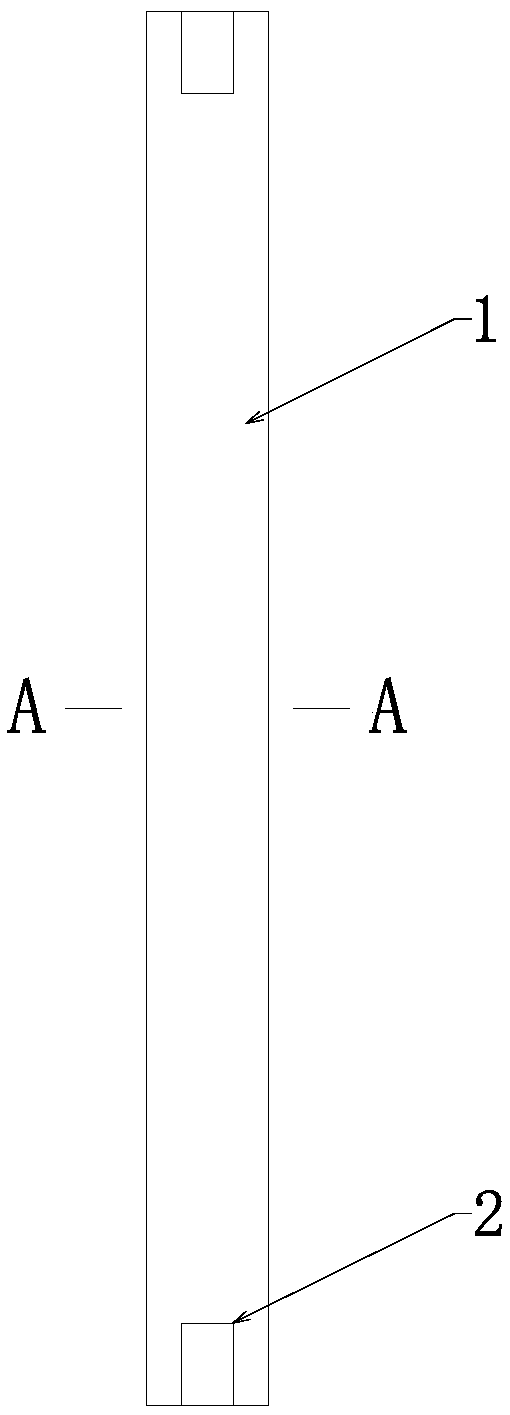
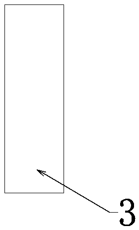
[0036] See attached figure 1 , 2 , 4 and 7, the present embodiment provides a zero-ohm grounding system, including 100 graphite bodies 1 connected end to end, the graphite bodies 1 are connected into a strip-shaped grounding system, and the adjacent graphite bodies 1 are connected by threads, and the threads The connection structure of the connection includes a graphite stud 3 and a threaded hole 2, and the end of the graphite body 1 is provided with the threaded hole 2.

[0037] The cross-sectional shape of the graphite body 1 is circular.

[0038] Adjacent graphite bodies 1 of the strip-shaped grounding system are connected through graphite studs 3 matched with threaded holes 2 at ends of graphite bodies 1 .

[0039] A preparation method of a zero-ohm grounding system, said preparation method comprising the following steps:

[0040] Step 1: Mix graphite, conductive carbon black, sodium silicate, and cement evenly in a weight ratio of 10:1:1:1, add water, mix and extrude, ...

Embodiment 2

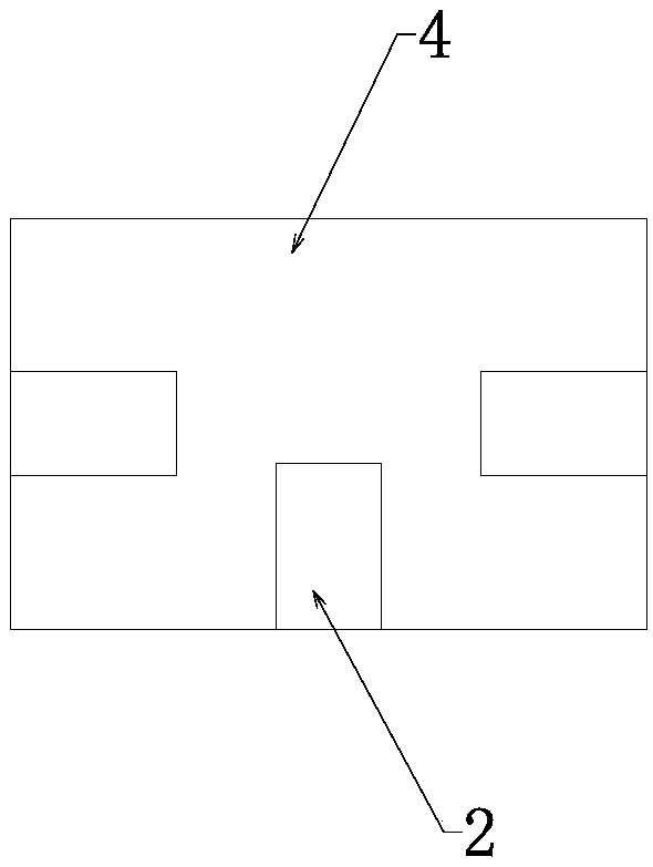
[0047] See attached figure 1 , 2 , 3, 5 and 7, the present embodiment provides a zero-ohm grounding system, including a number of graphite bodies 1 connected end to end, the graphite bodies 1 are connected into a plane mesh grounding system, and the adjacent graphite bodies 1 are connected by threads, so The connection structure of the threaded connection includes a graphite stud 3 and a threaded hole 2, and the end of the graphite body 1 is provided with the threaded hole 2.

[0048] The cross-sectional shape of the graphite body 1 is circular.

[0049] The planar net-like grounding system also includes a corner connector 4 with steering connection, the material of the corner connector 4 is the same as that of the graphite body 1, and the corner connector 4 is provided with not less than two threaded holes 2, and the corner The centerlines of the threaded holes 2 of the connector 4 have at least one pair of different directions.

[0050] A preparation method of a zero-ohm ...


PUM

PropertyMeasurementUnit
compressive strengthaaaaaaaaaa
flexural strengthaaaaaaaaaa

Abstract

The invention discloses a zero-ohm grounding system, comprises a plurality of graphite bodies connected end to end, wherein the graphite bodies are connected into a strip-shaped or planar reticulatedor stereoscopic reticulated grounding system, adjacent graphite bodies are connected through threads, the threaded connection structure comprises graphite studs and threaded holes, and the end parts of the graphite bodies are provided with threaded holes; The cross-sectional shapes of the graphite bodies include polygonal shapes, circular shapes and plum blossom shapes; The adjacent graphite bodies of the strip-shaped grounding system are connected through a graphite screw post matched with a threaded hole of an end part of the graphite body; The planar mesh and the three-dimensional mesh grounding system further comprises a turning angle connector of a steering connection, wherein the turning angle connector is provided with not less than two threaded holes, and the centerline of the threaded holes of the turning angle connector is at least provided with a pair of different directions; The invention has the advantages of light weight, low resistivity, excellent mechanical properties,good corrosion resistance, environmental protection and no pollution, long service life and wide application range.

Description

technical field [0001] The invention belongs to the technical field of electric grounding equipment, and in particular relates to a zero-ohm grounding system. Background technique [0002] Departments such as electric power, communication, and railway all lay metal materials in a large area or bury metal deeply when laying ground wires, in order to achieve its normal operation. The rapid development of modern electronic technology. In particular, precision instruments require very low grounding resistance, even close to zero resistance, but usually the soil quality is different, and the soil conductivity is also different. It is very difficult to achieve below 1Ω. Generally, chemical methods are used to change the conductivity of the soil to reduce the resistance of the soil. However, this method is complex and difficult to construct, and will cause environmental pollution. [0003] Another direct reason for the large ground resistance of the traditional ground wire device...

Claims


Application Information

Patent Timeline
Patent Type & Authority Applications(China)
IPC IPC(8): H01R4/66H01R43/00
CPCH01R4/66H01R43/00
Inventor 杨利涛胡佳
Owner 山西捷力通防雷科技有限公司
Learn More