Crystal salt separation purification system based on high-salt-containing high salt waste water

A technology of crystalline salt and high salt content, which is applied in water/sewage treatment, heating water/sewage treatment, water/sludge/sewage treatment, etc. It can solve the problems of not fully utilizing the effect of steam liquid film formation, etc., and achieve easy Effects of demolition, long flow distance, and increased recycling rate

Active Publication Date: 2018-12-18
ZHENGZHOU JIANGHE ENVIRONMENTAL PROTECTION TECH
View PDF5 Cites 5 Cited by
  • Summary
  • Abstract
  • Description
  • Claims
  • Application Information

AI Technical Summary

Problems solved by technology

It does not make full use of the stripping effect o...

Method used


Image

  • Crystal salt separation purification system based on high-salt-containing high salt waste water
  • Crystal salt separation purification system based on high-salt-containing high salt waste water
  • Crystal salt separation purification system based on high-salt-containing high salt waste water

Examples


Embodiment 1

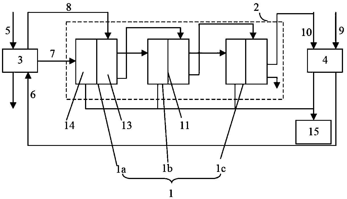
[0058] The invention provides an evaporation and concentration treatment unit for high-salt wastewater. The evaporative concentration treatment unit is used to perform evaporative concentration treatment on the saline wastewater that has been pretreated or pre-concentrated to obtain a higher concentration of salt solution, crystallized salt and / or distilled water. The evaporation and concentration treatment unit includes at least a multi-effect evaporation unit 2 formed by connecting several evaporators 1 in series, wherein the evaporation and concentration treatment unit also includes a first heat exchanger 3 and a second heat exchanger 4 for heat exchange.

[0059] figure 1 An evaporation concentration treatment unit with three evaporators is shown, and the number of evaporators can be selected and designed according to the treatment capacity of the evaporation concentration treatment unit or the type of waste water. For example, in order to achieve higher wastewater treatm...

Embodiment 2

[0067] Embodiment 2 is a further improvement on Embodiment 1, and repeated content will not be repeated here.

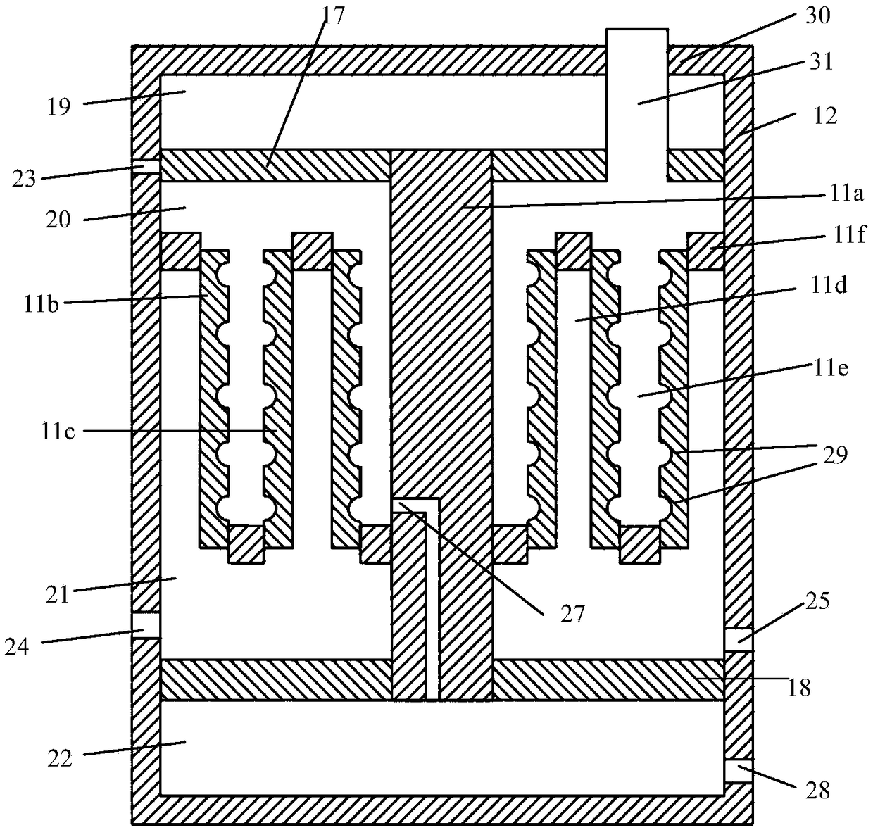
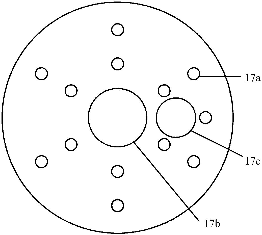
[0068] figure 2 A schematic diagram of the structure of the evaporator is shown. like figure 2 As shown, the shape of the housing 12 is defined by a hollow cylinder with one end open. In the axial direction parallel to the casing, the casing 12 is divided into four compartments by the distributor 17, the evaporation and condensation structure 11 and the installation web 18, wherein the distributor is installed on the inner wall of the casing near its open end Above, the installation web is installed near the other end of the housing 12 corresponding to its open end, and the evaporation and condensation structure 11 is installed on the area of ​​the housing corresponding between the distributor and the installation web. In the direction along the open end of the shell towards its closed end, a first compartment 19, a second compartment 20, a third compartment 21 ...

Embodiment 3

[0080] This embodiment is a further improvement on Embodiment 1 and Embodiment 2, and repeated content will not be repeated here.

[0081] Preferably, the evaporator of the present invention can be used alone or in series. For example, when three evaporators are connected in series to form a multi-effect evaporation unit, the structures of the first effect evaporator, the second effect evaporator and the third effect evaporator are exactly the same, and the only difference is that the first effect evaporator The air pressure in the third compartment of the evaporator, the second effect evaporator and the third effect evaporator is different from each other, wherein the air pressure in the third compartment of the first effect evaporator, the second effect evaporator and the third effect evaporator Set in steps of gradual reduction.

[0082] Preferably, the exhaust pipe of the first effect evaporator communicates with the second opening of the second effect evaporator, and the...


PUM

PropertyMeasurementUnit
Particle sizeaaaaaaaaaa

Abstract

The invention provides a crystal salt separation purification system based on high salthigh-salt-containing waste water. An outer case of an evaporator is separated into a first cavity and a second cavity through an evaporation-condensationevaporative condenser structure which is arranged inside the outer case of the evaporator and at least comprises a body, a first plate body and a second plate body; in the radial direction of the outer case, the first plate body and the second plate body are respectively connected to the body and the outer case through the respective first end parts and thesecond end parts and are distributed in a separated wayat an interval in a spiral bent form so as to form a first space and a second space which are not mutually communicated, wherein at least one groove which is communicated with the first end part and the second end part in a way of being not parallel to the radial direction of the outer case all the time according to the extending direction isarranged on the surface of each of the first plate body and the second plate body. The evaporator provided by the invention has the advantages that the evaporator has the longer flowing distance through being comparedin comparison with that of the vertically downward flowing process; in addition, the structure is compact; the larger heat exchange contact surface area is largerrealized; the secondary steam quantity generated by the evaporator can be obviously increased.

Description

technical field [0001] The invention belongs to the technical field of wastewater treatment equipment, and in particular relates to a crystal salt separation and purification system based on high-salt wastewater. Background technique [0002] Existing evaporators are mainly used to achieve evaporation and concentration of feed liquid, which are very typical chemical unit operation equipment in the industry, and are widely used in industrial production such as chemical industry, light industry, food, pharmaceuticals, seawater desalination, and sewage treatment. The existing evaporators are generally based on horizontal tube falling film and vertical tube falling film. In the vertical tube falling film evaporator, feed liquid is generally added to the evaporation chamber, and the solution is distributed to each heat exchange device through the film distribution device. Inside the tube, it flows downward in the form of a film along the inner wall of the heat exchange tube. Duri...

Claims


Application Information

Patent Timeline
IPC IPC(8): B01D1/26C02F1/04
CPCB01D1/26C02F1/048
Inventor 张建飞元西方何秉华刘丹丹
Owner ZHENGZHOU JIANGHE ENVIRONMENTAL PROTECTION TECH
Why Eureka
Try Eureka