High-efficiency textile fabric printing and dyeing treatment system and process

A textile fabric and processing system technology, applied in the direction of spray/jet textile material processing, textile material processing equipment configuration, etc., can solve the problems of low dye utilization rate, poor dyeing effect, uneven dyeing, etc., to improve utilization rate and increase The uniformity of dyeing and the effect of improving the dyeing effect

Active Publication Date: 2018-12-18
浙江盛邦化纤有限公司
View PDF7 Cites 6 Cited by
  • Summary
  • Abstract
  • Description
  • Claims
  • Application Information

AI Technical Summary

Problems solved by technology

[0005] One of the purposes of the present invention is to provide a high-efficiency printing and dyeing treatment system for textile fabrics in view of the deficiencies of the prior art, by setting the first dyeing mechanism and the second dyeing mechanism to extract and filter the thick dye solution at the bottom of the dye tank Spray on the surface of the fabric to form a double dyeing of dip dyeing and spray dyeing to improve the dyeing effect, and grind the filtered coarse particle dye in the alternate process to solve the problem of single fabric dyeing method, layered dyeing solution and poor dyeing effect Uneven dyeing and low dye utilization

Method used


Image

  • High-efficiency textile fabric printing and dyeing treatment system and process
  • High-efficiency textile fabric printing and dyeing treatment system and process
  • High-efficiency textile fabric printing and dyeing treatment system and process

Examples


Embodiment 1

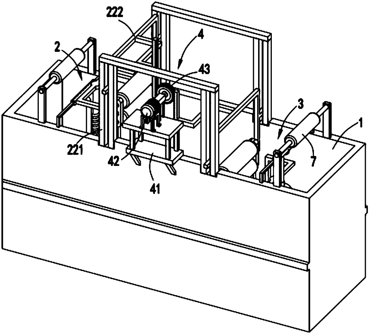
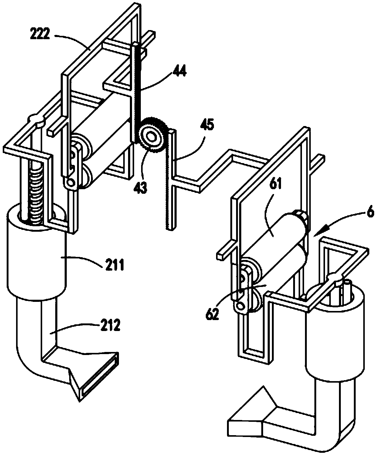
[0052] Such as Figure 1 to Figure 12 As shown, a high-efficiency printing and dyeing treatment system for textile fabrics includes a dye box 1, in which a first dyeing mechanism 2 and a second dyeing mechanism 3 are sequentially arranged in the dye box 1, and the first dyeing mechanism 2 and the second dyeing mechanism 3 both include a filtrate assembly 21 fixed on the inner wall of the dye box 1, a squeeze grinding assembly 22 arranged in the filtrate assembly 21, and a spraying assembly 23 arranged at the upper end of the filtrate assembly 21;

[0053] A driving mechanism 4 is arranged between the first dyeing mechanism 2 and the second dyeing mechanism 3, and the driving mechanism 4 is used to drive the front and rear extrusion grinding assemblies 22 to lift alternately, and the front and rear extrusion When the grinding assembly 22 moves upwards, the filtrate assembly 21 extracts the dye liquor at the bottom of the dye box 1, and when the front and back squeeze grinding a...

Embodiment 2

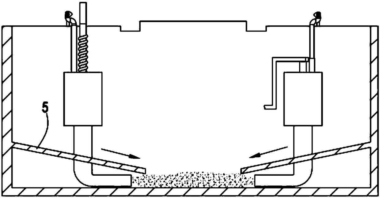
[0070] Such as figure 2 As shown, the components that are the same as or corresponding to those in the first embodiment are marked with the corresponding reference numerals in the first embodiment. For the sake of simplicity, only the differences from the first embodiment will be described below. The difference between the second embodiment and the first embodiment is that further, the suction pipe 212 is close to the bottom of the dye tank 1 and its end is bent towards the middle of the bottom of the dye tank 1, the bottom of the filtrate assembly 21 A guide plate 5 is provided, and the end of the guide plate 5 is inclined downward toward the middle of the bottom of the dye tank 1 .

[0071]By setting the guide plate 5 at the bottom of the dye box 1, some deposited coarse dyes and impurities travel along the guide plate 5 to the ports of the two suction pipes 212, which improves the efficiency of coarse dye collection and grinding.

Embodiment 3

[0073] like Figure 13 As shown, a high-efficiency printing and dyeing process for textile fabrics includes the following production steps:

[0074] (a) Dye liquor extraction process, when the squeeze grinding assembly 22 of the first dye spray mechanism 2 and the second dye spray mechanism 3 moves upward, the dye liquor deposited at the bottom of the dye tank 1 is drawn through the suction pipe 212 to the grinding chamber 211 Inside;

[0075] (b) One spraying process, the fabric to be printed and dyed is transported to the top of the first spraying mechanism 2 through the guide roller 7, and the extrusion grinding assembly 22 of the first spraying mechanism 2 moves downward to squeeze the dyeing material in the grinding chamber 211. liquid, so that the dyeing liquid is sprayed out through the spraying assembly 23 of the first spraying mechanism 2 to spray and dye the fabric once;

[0076] (c) Dip-dyeing process, the once-sprayed fabric is transported between the first dyein...


PUM


Abstract

The invention relates to a high-efficiency textile fabric printing and dyeing treatment system and process. The process involves a dye box, wherein a first spray dyeing mechanism and a second spray dyeing mechanism are arranged in the dye box, and each of the first spray dyeing mechanism and second spray dyeing mechanism comprises a filtrate assembly fixed on the inner wall of the dye box, a squeezing and grinding assembly arranged in the corresponding filtrate assembly and a spray dyeing assembly arranged at the upper end of the corresponding filtrate assembly; a driving mechanism is arrangedbetween the first spray dyeing mechanism and the second spray dyeing mechanism and drives the two squeezing and grinding assemblies to rise and fall alternately, the filtrate assemblies extract a dyeliquor at the bottom of the dye box when the squeezing and grinding assemblies move upward, the dye liquor in the filtrate assemblies is squeezed to be filtered when the squeezing and grinding assemblies move downward so that the dye liquor is sprayed from a front spray dyeing assembly and a rear spray dyeing assembly to dye a fabric, and the squeezing and grinding assemblies move downward continuously after dye liquor squeezing and spray dyeing are completed to grind the coarse-particle dye remaining in the filtrate assemblies. The high-efficiency textile fabric printing and dyeing treatmentsystem and process solve the problems that the fabric dyeing mode is single, the dye liquor is stratified, the dyeing effect is poor, dyeing is nonuniform, and the dye utilization rate is low.

Description

technical field [0001] The invention relates to the technical field of textile printing and dyeing equipment, in particular to a high-efficiency printing and dyeing treatment system and process for textile fabrics. Background technique [0002] Textile printing and dyeing, also known as dyeing and finishing, is a processing method and a general term for pretreatment, dyeing, printing, finishing, washing, etc. The existing dyeing methods include dip dyeing, spray dyeing, etc. When dip dyeing is carried out due to fuel The solubility of the dye is average, and it is easy to deposit after a long time. The dye at the bottom is heavy, while the dye solution on the surface is light, which affects the dyeing effect. [0003] A Chinese utility model patent with the authorized announcement number CN201810052331.8 discloses a textile printing and dyeing device, and specifically discloses that there are two printing and dyeing boxes on the support frame, and the up and down movement of...

Claims


Application Information

Patent Timeline
Patent Type & Authority Applications(China)
IPC IPC(8): D06B1/02D06B23/20
CPCD06B1/02D06B23/20
Inventor 张辰罗冬英谢富平
Owner 浙江盛邦化纤有限公司
Why Eureka
Try Eureka