
Heat pump compressed air energy storage system

A compressed air energy storage and heat pump technology, which is applied in heat pumps, lighting and heating equipment, steam engine devices, etc., can solve the problem of low energy density of compressed air energy storage systems, low energy storage density of compressed air energy storage technology, and incompatibility with green energy Development requirements and other issues, to achieve the effect of simple structure, high temperature, high heat storage density

Pending Publication Date: 2018-12-18
INST OF ENGINEERING THERMOPHYSICS - CHINESE ACAD OF SCI
View PDF0 Cites 15 Cited by
  • Summary
  • Abstract
  • Description
  • Claims
  • Application Information

AI Technical Summary

Problems solved by technology

However, the energy storage density of compressed air energy storage technology is low, and the difficulty lies in the need for suitable places where compressed air can be stored, such as sealed caves or abandoned mines, etc.
Moreover, the compressed air energy storage system still relies on the burning of fossil fuels to provide heat sources. On the one hand, it faces the threat of the gradual depletion of fossil fuels and rising prices; Zero emissions), renewable energy development requirements
[0006] In order to solve the main problems faced by traditional compressed air energy storage systems, domestic and foreign scholars have carried out advanced adiabatic compressed air energy storage systems (AACAES), surface compressed air energy storage systems (SVCAES), compressed air storage Energy storage system (AACAES) and air-steam combined cycle compressed air energy storage system (CASH), etc., make the compressed air energy storage system basically avoid burning fossil fuels, but the energy density of the compressed air energy storage system is still very low, requiring a large storage chamber

Method used


Image

  • Heat pump compressed air energy storage system

Examples


Embodiment Construction

[0037] In order to make the object, technical solution and advantages of the present invention clearer, the present invention will be further described in detail below with reference to the accompanying drawings and examples.

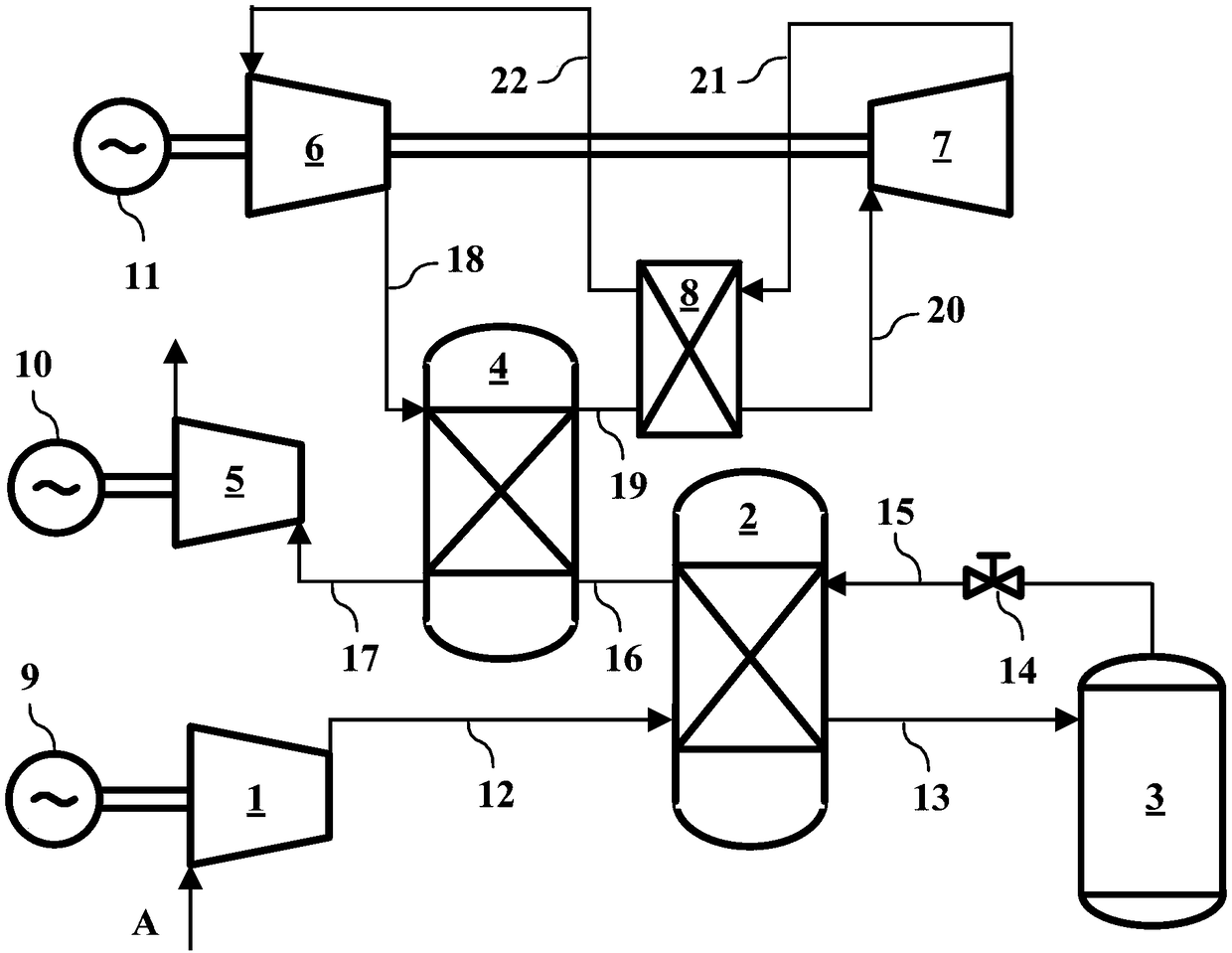
[0038] Such as figure 1 As shown, the heat pump compressed air energy storage system of the present invention consists of an air compressor unit 1, a medium and low temperature heat storage / heat exchanger 2, an air storage tank 3, a high temperature heat storage / heat exchanger 4, an air expansion unit 5, and a heat pump cycle compression Unit 6, heat pump cycle expansion unit 7, heat exchanger 8, driving motor 9, generator 10, heat pump driving motor 11, valve 14 and multiple pipelines 12, 13, 15-22.

[0039] Heat pump cycle compressor unit 6, high temperature heat storage / heat exchanger 4, heat exchanger 8, heat pump cycle expansion unit 7 and pipelines 18, 19, 20, 21, 22 form a heat pump high temperature heating loop. The heat pump drive motor 11 is ...


PUM


Abstract

The invention discloses a heat pump compressed air energy storage system. The heat pump compressed air energy storage system comprises a heat pump high-temperature heating cycle loop and a compressedair energy storage and energy release loop. The heat pump compressed air energy storage system compresses the air into a high-pressure state through off-peak (low-price) electricity of a power station, stores air compression heat and produces and stores high-temperature heat through the heat pump high-temperature heating cycle loop. During the period of electricity consumption peak, the high-pressure compressed air absorbs the stored compression heat and the stored high-temperature heat energy in sequence and then is fed into an expansion machine to drive a power generator to generate electricity. The heat pump compressed air energy storage system provided by the invention has the advantages of being simple in structure, high in efficiency, strong in flexibility, suitable for peak regulation of a power grid and various types of renewable energy source power stations, free of generation of greenhouse gases and the like.

Description

technical field [0001] The invention belongs to the technical field of energy storage, and relates to a heat pump compressed air energy storage system, which is an energy storage system based on a heat pump cycle and compressed air to store energy and utilize the stored energy to generate electric energy. Background technique [0002] In recent years, renewable energy is gradually becoming an important source of new electricity, and major changes have taken place in the grid structure and operation mode. With the increasing popularity of renewable energy (wind energy, solar energy, etc.), and the urgent need for grid peak regulation, improving grid reliability, and improving power quality, the importance of power energy storage systems has become increasingly prominent. Energy storage is an important component and key supporting technology of smart grids, energy systems with a high proportion of renewable energy, and "Internet +" smart energy (hereinafter referred to as ener...

Claims


Application Information

Patent Timeline
IPC IPC(8): F01K27/00F01K3/00F25B30/02
CPCF01K3/00F01K27/00F25B30/02
Inventor 王亮林曦鹏陈海生凌浩恕陈磊
Owner INST OF ENGINEERING THERMOPHYSICS - CHINESE ACAD OF SCI
Learn More