A carbon dioxide heat pump device

A technology of heat pump device and throttling device, which is applied in the direction of refrigeration and liquefaction, lighting and heating equipment, refrigeration components, etc., and can solve the problems of affecting the heating capacity of the heat pump system, small temperature difference between refrigerant and ice layer, general ice melting effect, etc. , to achieve the effect of reducing installation and adjustment workload, stable heating operation and good adaptability

Active Publication Date: 2021-12-07
浙江盾安机电科技有限公司
View PDF0 Cites 0 Cited by
  • Summary
  • Abstract
  • Description
  • Claims
  • Application Information

AI Technical Summary

Problems solved by technology

[0003] CO 2 When heat pumps are used in low-temperature areas, there will always be frosting, especially in extremely cold areas. Due to the low temperature, the water after defrosting in the evaporator cannot flow away in time. Freezing, the ice layer will affect the heating capacity of the heat pump system
In the prior art, it has been proposed to introduce the outlet of the gas cooler into the subcooling section and go to the bottom of the evaporator to prevent freezing, but in a low temperature environment, the temperature of the inlet water is usually relatively low, and the CO 2 There is a large temperature glide in the heat exchange in the gas cooler, so that the gas cooler outlet CO 2 The temperature of the refrigerant and the inlet water is close to or slightly higher than that of the fluorine refrigerant, which has a higher outlet condensation temperature, and the outlet CO 2 After the refrigerant exchanges heat with the inlet water, the gas cooler exports CO 2 The temperature difference between the refrigerant and the ice layer is actually small, and the ice melting effect is average

Method used


Image

  • A carbon dioxide heat pump device

Examples


Embodiment 1

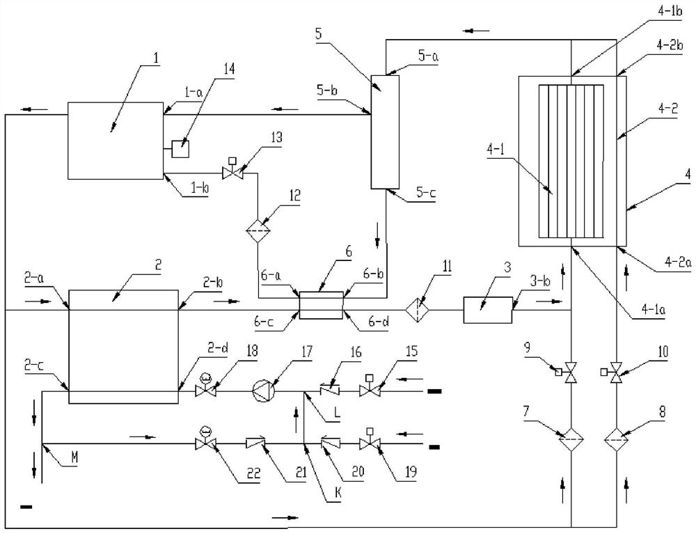
[0023] Embodiment one, such as figure 1 As shown, a CO 2 A heat pump device, including a main heating cycle pipeline and a compressor 1, a gas cooler 2, an oil heat exchanger 6, a first filter 11, a throttling device 3, and an evaporator 4 sequentially connected to the main heating cycle pipeline , Gas-liquid separator 5. CO 2 When the heat pump device is in heating operation, the CO in the main heating cycle pipeline 2 The refrigerant is compressed by the compressor 1 into high-temperature and high-pressure gas, which exits from the outlet of the compressor, enters the gas cooler 2 through the inlet 2-a of the gas cooler, and becomes a high-pressure gas with a lower temperature after heat exchange and exits the gas cooler. 2-b, enter the oil heat exchanger 6 through the oil heat exchanger inlet 6-c, exit from the oil heat exchanger outlet 6-d, and then pass through the first filter 11 and the throttling device 3 to become a low-temperature and low-pressure gas Or the liqu...

Embodiment 2

[0027] Embodiment 2, on the basis of Embodiment 1, the CO 2 The heat pump device also includes a defrosting circulation pipeline and a compressor 1 connected to the defrosting circulation pipeline, a second filter 7, a first solenoid valve 9, a throttling device 3, an evaporator 4, and a gas-liquid separator 5. The first electromagnetic valve 9 is connected to the outlet 3-b of the throttling device and at the same time connected to the inlet 4-1a of the evaporator, and then connected to the inlet 5-a of the gas-liquid separator, and returns to the compressor from the outlet 5-b of the gas-liquid separator. Machine return air port 1-a.

[0028] When the CO 2 When the heat pump device operates at a low ambient temperature, the surface of the evaporator is frosted, the first solenoid valve 9 is opened, the throttling device 3 is closed, and the high-temperature and high-pressure CO 2 The gas passes through the second filter 7 and the first electromagnetic valve 9 from the outl...

Embodiment 3

[0030] Embodiment three, on the basis of embodiment one, the CO 2 The heat pump device also includes a compressor refrigerating oil independent oil return circulation pipeline and a compressor 1 connected to the compressor refrigerating oil independent oil return circulation pipeline, a gas-liquid separator 5, an oil heat exchanger 6, a fourth filter 12, The fifth solenoid valve 13. When CO 2 When the heat pump device is running at a low ambient temperature or under variable frequency conditions, when the oil level sensor 14 on the compressor 1 detects the lower limit of the oil level, the CO 2 Controlled by the main control circuit of the heat pump device, the fifth solenoid valve 13 is opened, and the refrigerated oil separated by the gas-liquid separator 5 comes out from the outlet 5-c of the gas-liquid separator, and enters the oil for heat exchange through the inlet 6-b of the oil heat exchanger. The device 6, after heat exchange, heats the refrigerated oil, comes out f...


PUM


Abstract

The invention discloses a carbon dioxide heat pump device, which comprises a compressor, a gas cooler, an oil heat exchanger, a first filter, a throttling device, an evaporator, and a gas-liquid separator sequentially connected to a main heating cycle pipeline. The CO 2 The heat pump device also includes an ice-melting circulation pipeline and a compressor connected to the ice-melting circulation pipeline, a third filter, a second electromagnetic valve, an evaporator, and a gas-liquid separator. When the bottom of the evaporator freezes, the second Solenoid valve, high temperature and high pressure CO 2 The gas passes through the third filter and the second solenoid valve from the outlet of the compressor, and enters the independent pipeline in the lower part of the evaporator to melt the ice layer at the bottom of the evaporator, and then the generated heat CO 2 The vapor returns to the gas return port of the compressor through the gas-liquid separator to form CO 2 Melting cycle of heat pump unit. CO of the present invention 2 The heat pump device operates at a low ambient temperature, which can realize rapid ice melting and make the heating operation of the system stable.

Description

technical field [0001] The invention relates to the technical field of air conditioning, in particular to CO 2 heat pump unit. Background technique [0002] CO 2 Heat pump technology uses natural CO 2 As a circulating working fluid, it adopts a transcritical circulation method to release heat under supercritical conditions. The heat release is a variable temperature process with a large temperature glide, which matches the required variable temperature heat source very well. It is a special kind of Lorenz cycle. [0003] CO 2 When heat pumps are used in low-temperature areas, there will always be frosting, especially in extremely cold areas. Due to the low temperature, the water after defrosting in the evaporator cannot flow away in time. Freezing, the ice layer will affect the heating capacity of the heat pump system. In the prior art, it has been proposed to introduce the outlet of the gas cooler into the subcooling section and go to the bottom of the evaporator to p...

Claims


Application Information

Patent Timeline
Patent Type & Authority Patents(China)
IPC IPC(8): F25B9/00F25B47/02F25B41/24F25B41/20F25B41/31F25B41/37F25B31/00
CPCF25B9/008F25B31/004F25B47/022F25B2309/06F25B2600/25F25B41/20F25B41/30
Inventor 潘祖栋汪新民陈松
Owner 浙江盾安机电科技有限公司
Why Eureka
Try Eureka