Method for predicting the wear life of stamping dies with full-time wear accumulation

A stamping die and wear life technology, applied in the field of die stamping, can solve the problems of ignoring the influence of contact stress and slip speed, low prediction accuracy, etc., to reduce the complexity of the problem and improve the efficiency.

Pending Publication Date: 2018-12-18
GUANGXI AISHENG CHUANGZHI SCI & TECH CO LTD
View PDF0 Cites 4 Cited by
  • Summary
  • Abstract
  • Description
  • Claims
  • Application Information

AI Technical Summary

Problems solved by technology

[0004] At present, the Archard theory is widely used for numerical simulation of die wear, but the traditional Archard model ignores the influence of the wear process on the contact stress and slip velocity, resulting in low prediction accuracy

Method used


Image

  • Method for predicting the wear life of stamping dies with full-time wear accumulation
  • Method for predicting the wear life of stamping dies with full-time wear accumulation
  • Method for predicting the wear life of stamping dies with full-time wear accumulation

Examples


Embodiment 1

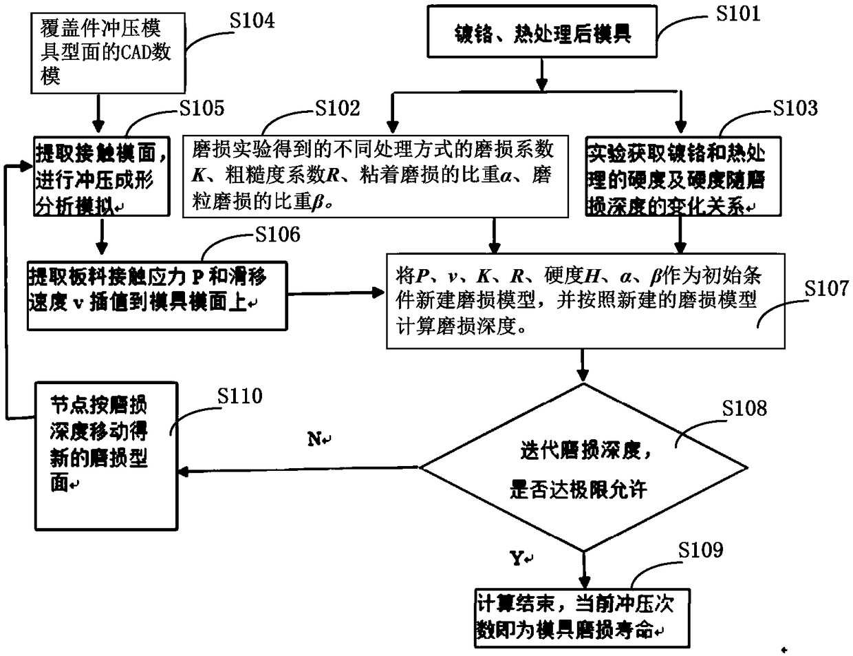
[0044] The invention provides a method for predicting the wear life of a stamping die with full-time wear accumulation, and its implementation process is as follows figure 1 shown, including the following steps:

[0045] Step S101, taking mold materials with different surface treatments, such as mold materials that undergo electrochrome plating after laser quenching (herein referred to as the first mold material) and mold materials that have only undergone laser quenching heat treatment (herein referred to as the first mold material) as the second mold material).

[0046] Step S102, using a wear testing machine to measure the wear coefficient (indicated by K), roughness coefficient (indicated by R), specific gravity α of adhesive wear and specific gravity β of abrasive wear of the first mold material and the second mold material respectively.

[0047] Step S103, conducting electrochrome plating experiment and laser quenching finite element simulation experiment on the first m...

example

[0074] Taking the die used for punching the outer panel of the engine cover of an automobile (referred to as the outer panel die of the engine cover in this article) as an example, the prediction method proposed in this patent is used to predict the wear life of the outer panel die of the engine cover. The specific implementation method is as follows :

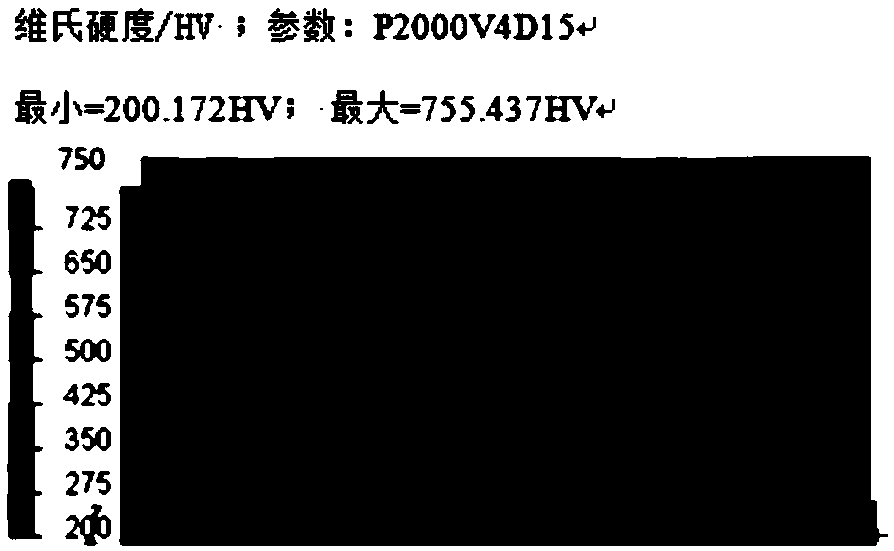
[0075] 1) Through the electrochrome plating experiment and laser quenching simulation of the engine cover outer plate mold material, the relationship between the hardness and wear depth of the engine cover outer plate mold material in the process of laser quenching and electrochrome plating treatment is obtained , it can be seen that the hardness of the engine cover outer plate mold material shows a gradient trend as the wear depth gradually increases from the outermost surface to the core.

[0076] The relationship between the Brinell hardness of the engine cover outer plate mold and the wear depth is expressed by the followi...


PUM


Abstract

The invention relates to a full-time wear accumulative wear life prediction method of a stamping die, which adopts a wear testing machine to separately measure wear coefficient K, roughness coefficient R, specific gravity alpha of adhesive wear and specific gravity beta of abrasive wear of a plurality of die materials with different treatment modes; through the finite element simulation experiment, the hardness H of the die material and the relationship between the hardness and the wear depth gradient were obtained. According to the die surface CAD digital model of the stamping die, the contact die surface of the stamping die and the stamped sheet metal is extracted, and the contact stress P of the contact die surface and the slip speed v of the stamped sheet metal is extracted relative tothe die through numerical simulation of stamping forming; a new wear model is established and the wear depth is calculated by using the above parameters as boundary conditions. When the wear depth ofthe stamping wear model obtained by iteration reaches the limit allowable value, it is confirmed that the current stamping times is the die wear life. The invention solves the technical problem thatthe prediction accuracy of the traditional Archard model is not high.

Description

technical field [0001] The invention relates to a die stamping technology, in particular to a method for predicting the wear life of a stamping die with full-time wear accumulation. Background technique [0002] Stamping dies are an important tool for processing automobile sheet metal parts. The cost of stamping dies can account for more than 15% of the cost of auto parts. Therefore, the life of stamping dies for automobile sheet metal parts has always been an important factor in evaluating the cost and efficiency of automobile production. . [0003] Die wear is a direct manifestation of affecting the life of stamping dies. Die wear can cause part dimensional changes or surface scratches, resulting in off-spec parts. Generally speaking, the failure and scrapping of stamping dies are mostly caused by plastic deformation, friction and wear, and fatigue cracking, among which 70% are directly or indirectly caused by die wear. Therefore, how to accurately predict the wear part...

Claims


Application Information

Patent Timeline
Patent Type & Authority Applications(China)
IPC IPC(8): G06F17/50
CPCG06F30/20G06F30/17
Inventor 聂昕
Owner GUANGXI AISHENG CHUANGZHI SCI & TECH CO LTD
Why Eureka
Try Eureka