

A batch loading device and a cell flexible forming line
An equipment and batch technology, applied in the fields of battery assembly, climate sustainability, secondary battery manufacturing, etc., can solve problems such as affecting production efficiency, slow feeding speed, battery fire, etc., to save equipment costs and feeding materials. High efficiency and increased productivity
- Summary
- Abstract
- Description
- Claims
- Application Information
AI Technical Summary
Problems solved by technology
Method used
Image

Examples
Embodiment 1
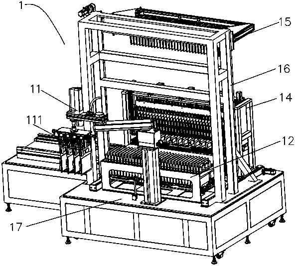
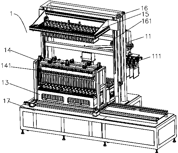
[0023] refer to figure 1 and figure 2 , a batch feeding equipment, including a feeding manipulator 11, a temporary storage tool 12, a transfer tool 13 and a transfer mechanism 14. The feeding manipulator 11 is arranged next to the temporary storage tooling 12, and materials are fed into the temporary storage tooling 12. The temporary storage tooling 12 has a large space and many positions, and can store multiple materials temporarily. The feeding manipulator takes 11 minutes Temporary storage tooling 12 is filled with material repeatedly. The temporary storage tool 12 and the transfer tool 13 are arranged side by side, and are generally fixed on the base 17 one in front of the other. The transfer tool 13 is provided with a detachable and transferable holding jig, and each time the holding jig is filled with material, it can be removed from the transfer tool 13 by other transfer equipment, and then put into another holding jig for reloading. The containing jig is consistent...
Embodiment 2
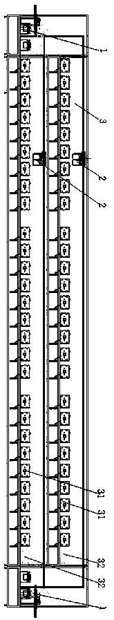
[0029] refer to image 3 , a battery flexible forming line based on the batch feeding equipment in Embodiment 1, including batch feeding equipment 1, transfer equipment 2 and forming equipment 3, the front end and rear end of the forming equipment 3 are each equipped with a batch feeding equipment Equipment 1, the batch loading equipment 1 at the front end is used for loading, and the batch loading equipment 1 at the back end is used for unloading. The transfer device 2 is slidably arranged above the chemical conversion device 3, and is used to transfer the holding jig in the transfer tooling 13 between the batch feeding device 1 and the transfer device 2, that is, to transfer the material in the holding jig to the chemical conversion device 3 processing, after completion, move to the back-end batch feeding equipment 1 for unloading.
[0030] refer to image 3 , the chemical conversion equipment 3 is a double-layer structure, the batch feeding equipment 1 includes a lifting ...
PUM
 Abstract
Description
Claims
Application Information