An intelligently tunable energy wireless transmission system
A wireless transmission and energy technology, applied in transportation and packaging, electric vehicles, current collectors, etc., can solve the problem that the position and distance between the transmitting unit and the receiving unit cannot be fixed, the transmitting unit and the receiving unit cannot resonate, the transmission distance and the transmission efficiency are affected and other issues to achieve the effect of reducing impact, reducing system cost, and improving the adjustment range
- Summary
- Abstract
- Description
- Claims
- Application Information
AI Technical Summary
Problems solved by technology
Method used
Image
Examples
Embodiment 1
[0028] Embodiment 1 Overall structure of the present invention
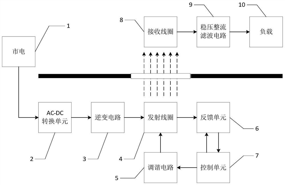
[0029] Overall structural block diagram of the present invention is as figure 1 Shown:
[0030] The input end of the AC-DC conversion unit 2 is connected to the mains 1, the output end is connected to the input end of the inverter circuit 3, the output end of the inverter circuit 3 is connected to the transmitting coil 4, and the transmitting coil 4 is also connected to the input of the tuning circuit 5 end and the input end of the feedback unit 6 are connected, the output end and the enabling end of the feedback unit 6 are respectively connected with the input end and the control end of the control unit 7, and the output end of the control unit 7 is connected with the input end of the tuning circuit 5; the receiving coil 8 is connected to the input terminal of the voltage stabilizing rectification filter circuit 9, and the output terminal of the voltage stabilizing rectification filter circuit 9 is connected to...
Embodiment 2
[0033] Embodiment 2 Feedback unit
[0034] The circuit structure of the feedback unit 6 is as figure 2 As shown, the 1 port of the relay K1 is used as the input terminal of the feedback unit 6, which is recorded as the port In_Volt, and is connected to the transmitting coil 4, and the 3 port of the relay K1 is used as the enabling terminal of the feedback unit 6, which is recorded as the port S_Drive, and is connected with the control unit 7 The control terminal of the relay K1 is connected to the anode of the diode D1; the 2 ports of the relay K1 are connected to the power supply VCC; the cathode of the diode D1 is connected to one end of the resistor R1, one end of the resistor R2, and one end of the capacitor C1; the other end of the resistor R1 is connected to the capacitor C1 The other end of the resistor R2 is connected to GND; the other end of the resistor R2 is connected to one end of the resistor R3 and one end of the capacitor C2, and is used as the output end of th...
Embodiment 3
[0036] Embodiment 3 control unit
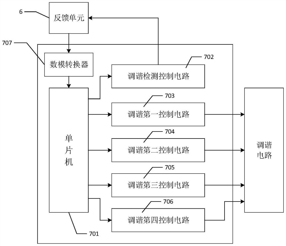
[0037] The structure of the control unit 7 is as image 3 As shown, the output end of the analog-to-digital converter 707 is connected to the single-chip microcomputer 701, and the input end is used as the input end of the control unit 7, and is connected to the output end (ie, port Out_Volt) of the feedback unit 6, and the single-chip microcomputer 701 is also connected to the first control circuit 703 respectively. , the input end of the second control circuit 704, the third control circuit 705, the fourth control circuit 706, and the fifth control circuit 702 are connected; the output end of the fifth control circuit 702 is used as the control end of the control unit 7, and the feedback unit 6 The enable terminal (ie, the port S_Drive) is connected, and the output terminals of the first control circuit 703, the second control circuit 704, the third control circuit 705, and the fourth control circuit 706 (ie, the port Out_Drive of each cont...
PUM
 Abstract
Description
Claims
Application Information
 - R&D
- Intellectual Property
- Life Sciences
- Materials
- Tech Scout
- Unparalleled Data Quality
- Higher Quality Content
- 60% Fewer Hallucinations
Browse by: Latest US Patents, China's latest patents, Technical Efficacy Thesaurus, Application Domain, Technology Topic, Popular Technical Reports.
© 2025 PatSnap. All rights reserved.Legal|Privacy policy|Modern Slavery Act Transparency Statement|Sitemap|About US| Contact US: help@patsnap.com


