A bridgeless three-rectifier Boost power supply circuit

A power supply circuit and circuit technology, applied in the direction of high-efficiency power electronic conversion, electrical components, adjusting electrical variables, etc., can solve the problems of EMI noise, floating AC input line, complex control of bridgeless PFC circuit, etc., to achieve anti-surge capability Strong, strong anti-interference, to achieve the effect of active power factor correction

Inactive Publication Date: 2018-12-18
SHANGHAI TUITUO TECH CO LTD
View PDF6 Cites 7 Cited by
  • Summary
  • Abstract
  • Description
  • Claims
  • Application Information

AI Technical Summary

Problems solved by technology

[0008] In addition to the complex control of the bridgeless PFC circuit, the biggest challenge of the bridgeless PFC circuit in practical applications is the problem of EMI noise. Compared with the traditional Boost circuit, this is caused by the floating ground of the AC input line by the high-frequency switching elements. of

Method used


Image

  • A bridgeless three-rectifier Boost power supply circuit
  • A bridgeless three-rectifier Boost power supply circuit
  • A bridgeless three-rectifier Boost power supply circuit

Examples


Embodiment 1

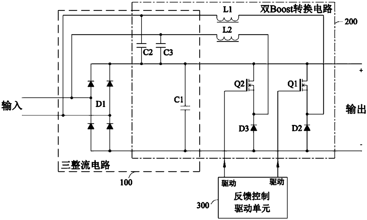
[0044] A bridgeless three-rectification Boost power supply circuit shown in this embodiment, see image 3 As shown, it includes three rectification circuits 100, a double Boost conversion circuit 200, a feedback control drive unit 300, and an energy storage capacitor C1.

[0045] The dual Boost conversion circuit includes a first Boost circuit and a second Boost circuit.

[0046] The first Boost circuit includes a first Boost capacitor C2, a first Boost inductor L1, a first Boost switch element Q1, and a first Boost rectifier element (diode D2 is selected). When the first Boost switch element Q1 is turned on, the first Boost inductor L1, the first Boost switching element Q1 and the first Boost capacitor C2 form a first Boost loop in which the voltage on the first Boost capacitor C2 charges the first Boost inductor L1; when the first Boost switching element is turned off, the first Boost inductor L1 , the first Boost rectifier element, the first Boost capacitor, and the energy...

Embodiment 2

[0073] The difference between this embodiment and Embodiment 1 is that the first Boost rectifier element and the second Boost rectifier element use switching elements, which are respectively switching element Q3 and switching element Q4, see Figure 8 , the on and off of the switching element Q3 and the switching element Q4 are controlled by the feedback control driving unit.

[0074] The conduction loss of the switching element is Irms 2 *Rds(on), the conduction loss of the rectifier element is Vf*Iavg.

[0075] The current device technology, because the Rds(on) of the switching element FET, etc. is getting smaller and smaller, so in small and medium power applications, due to the low loss, it is used to replace the rectifier element to improve efficiency. The disadvantage is that it is expensive and requires additional drive control circuit. In high-power applications, since the Vf value of the rectifier element does not change too much with the increase of current, the lo...

Embodiment 3

[0078] In this embodiment, the first BUCK inductance Ls1, the second BUCK inductance Ls2 and the filter capacitor Cs1 are added on the basis of the first embodiment, and the first Boost switching element Q1 and the first Boost rectifying element (diode D2 is selected) form the first BUCK The bridge arm, the first BUCK bridge arm, the first BUCK inductance Ls1 and the filter capacitor Cs1 form the first BUCK converter, the first BUCK converter is used to perform BUCK conversion output on the voltage on the energy storage capacitor; the second Boost switching element Q2 and The second Boost rectifier element (diode D3 is selected) forms the second BUCK bridge arm, the second BUCK bridge arm, the second BUCK inductance and the filter capacitor Cs1 form the second BUCK converter, and the second BUCK converter is used for the energy storage capacitor voltage for BUCK conversion output, see Figure 9 shown.


PUM


Abstract

The invention discloses a bridgeless three-rectifier boost power supply circuit, includes three rectifying circuits, two Boost capacitors, energy storage capacitors, two Boost conversion circuits andfeedback control driving unit. The three rectifying circuits rectify and charge the energy storage capacitors, and charge the two Boost capacitors respectively when the input voltage is positive and negative. When the input voltage is positive or negative, the double Boost converter alternately charges the storage capacitor by superposing the voltage on the Boost inductor and the Boost capacitor,thus realizing the Boost boost conversion function. In the three-rectifier circuit, only one diode is used to charge the Boost capacitor, so the effect of bridge-less PFC is achieved. Rationally arrange the connection position of the input surge suppression circuit so that it has zero loss. As the invention follows the input structure of the traditional BoostPFC, the invention has better EMI effect than the traditional bridgeless PFC circuit.

Description

technical field [0001] The invention relates to a switching power supply circuit with the advantages of high efficiency, high reliability, low EMI noise, strong anti-interference and anti-surge ability, etc., which can realize the function of correcting the input power factor of alternating current and boosting the output. Background technique [0002] The AC-DC power supply of electrical equipment connected to the AC grid must meet the mandatory requirements of IEC61000-3-2 for current harmonics. For different equipment and applications, IEC61000-3-2 proposes Class A, Class B, Class C, and Class D current harmonic limit standards. [0003] The current switching power supply technology mainly uses the Boost circuit ( figure 1 ) plan to deal with it. [0004] In order to achieve high efficiency, Bridgeless PFC and Totem Pole (TotemPole) PFC circuits are also used. The core is still the Boost circuit. In the input circuit of the traditional Boost PFC, the two diodes passing ...

Claims


Application Information

Patent Timeline
Patent Type & Authority Applications(China)
IPC IPC(8): H02M3/158H02M7/217H02M1/42H02M1/44
CPCH02M1/4225H02M1/44H02M3/1584H02M7/217H02M3/1586Y02B70/10
Inventor 李韧红
Owner SHANGHAI TUITUO TECH CO LTD
Why Eureka
Try Eureka