High-temperature washing and deacidifying system

A high-temperature, washing tower technology, applied in the field of high-temperature flue gas treatment, can solve the problems of no anti-corrosion of dilute acid, increase one-time investment, increase operating cost, etc. Corrosion and alkali corrosion resistance, the effect of reducing moisture content

Pending Publication Date: 2018-12-21
CHINA ENFI ENGINEERING CORPORATION
View PDF0 Cites 0 Cited by
  • Summary
  • Abstract
  • Description
  • Claims
  • Application Information

AI Technical Summary

Problems solved by technology

[0004] Steel washing and deacidification towers include ordinary carbon steel and stainless steel washing and deacidification towers. Although their strength will not change at a temperature of 300°C, their biggest disadvantage is that they have no corrosion protection for dilute acids (especially dilute hydrochloric acid). Ordinary carbon steel and stainless steel corrode very fast under dilute acid immersion (especially in dilute hydrochloric acid immersion), and the service life of a 5mm-6mm steel washing and deacidification tower is generally 3 months to 12 months
[0005] For FRP washing and deacidification towers, the existing equipment can only handle flue gas whose inlet temperature is lower than 80°C. If the inlet flue gas temperature is higher than 80°C, the material of the FRP body will soften due to the temperature rise, and its strength will be greatly reduced. At 100°C, the equipment will be scrapped, and in serious cases, it will cause personal safety accidents
Therefore, if the temperature of the flue gas to be treated is higher than 80°C, a flue gas temperature regulating tower must be installed in front of the FRP washing and deacidifying tower to reduce the temperature of the flue gas entering the FRP washing and deacidifying tower to below 80°C, increasing the temperature of the flue gas. One-time investment, but also increased operating costs

Method used


Image

  • High-temperature washing and deacidifying system

Examples


Embodiment

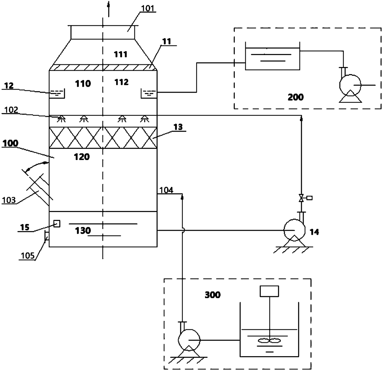
[0054] The height ratio of the defogging area, the spraying area, and the reaction area in the FRP washing tower is 1:4:6, and the distance between the bottom of the high-temperature flue gas inlet and the upper end of the alkali liquid level in the reaction area is 1.0m. The angle between the intake direction of the high-temperature flue gas inlet and the central axis of the FRP scrubber is 55°

[0055] The flue gas containing harmful components at a temperature of 80°C-250°C is introduced into the reaction zone of the FRP washing tower through the high-temperature flue gas inlet, and the flue gas rushes into the lye in the reaction zone at a speed of 12m / s-15m / s, and the The action of lye realizes preliminary dust removal, deacidification and temperature reduction, and then the flow direction of the flue gas is changed from downward to upward, and the temperature of the flue gas is reduced by 10°C to 20°C. At the same time, the lye is sprayed evenly through the circulating l...


PUM

PropertyMeasurementUnit
thicknessaaaaaaaaaa

Abstract

The invention discloses a high-temperature washing and deacidifying system which comprises a glass fiber reinforced plastic washing tower, a water supplementary device and an automatic alkaline solution supplementary device. A defogging area, a spraying area and a reaction area are defined in the glass fiber reinforced plastic washing tower from top to bottom; the defogging area is provided with aclean gas outlet; a defogging device is arranged in the defogging area and located under the clean gas outlet; a high-temperature overflow water film protection device is arranged on the inner wall of the defogging area and located under the defogging device; the spraying area is provided with a recycled alkaline solution spraying port; the recycled alkaline solution spraying port is connected with the lower part of the reaction area through a circulating pump; a filler layer is arranged on the spraying area and located under the alkaline solution spraying port; the reaction area is providedwith a high-temperature flue gas inlet, an alkaline solution supplementary inlet, a pH detector and a drain outlet; the water supplementary device is connected with the high-temperature overflow waterfilm protection device; the automatic alkaline solution supplementary device is connected with the alkaline solution inlet.

Description

technical field [0001] The invention belongs to the field of high-temperature flue gas treatment, in particular, the invention relates to a high-temperature washing and deacidification system. Background technique [0002] In metallurgy, building materials, domestic waste incineration and hazardous waste incineration industries, after the flue gas undergoes dry and / or semi-dry deacidification and dust removal, there are still a small amount of harmful components in the flue gas, in order to meet higher standards of environmental protection requirements , it is necessary to install a washing and deacidification tower in the follow-up to carry out deep removal of harmful components in the flue gas. And the temperature of flue gas after dry and / or semi-dry treatment is generally kept above 150 degrees Celsius. The purpose is to ensure that the temperature of flue gas is above the acid dew point and prevent corrosion of processing equipment. Therefore, when these high-temperatu...

Claims


Application Information

Patent Timeline
Patent Type & Authority Applications(China)
IPC IPC(8): B01D53/78B01D53/40B01D53/96B01D47/14
CPCB01D53/78B01D47/14B01D53/40B01D53/96B01D2247/04B01D2247/10B01D2258/0283
Inventor 彭孝容陈德喜高玉萍刘霞程虎
Owner CHINA ENFI ENGINEERING CORPORATION
Why Eureka
Try Eureka