Slurry stirring device for spinning assembly line

A stirring device and assembly line technology, applied to mixers with rotating stirring devices, mixer accessories, drive agitator dissolution, etc., can solve problems such as insufficient dye mixing, affecting use effect and practical performance, poor coloring, etc.

Inactive Publication Date: 2018-12-21
安徽职业技术学院
View PDF6 Cites 2 Cited by
  • Summary
  • Abstract
  • Description
  • Claims
  • Application Information

AI Technical Summary

Problems solved by technology

The current mixing tank only uses the stirring paddle for stirring. Such a mixing tank cannot effectively stir the dye fully, resulting in uneven dyeing and poor coloring, and the bottom and inner wall of the mixing tank tend to accumulate part of the dye during the stirring process. Can't mix better, resulting in waste of resources
[0003] In addition, during the stirring process of the slurry,

Method used


Image

  • Slurry stirring device for spinning assembly line
  • Slurry stirring device for spinning assembly line
  • Slurry stirring device for spinning assembly line

Examples


Example Embodiment

[0021] Examples:

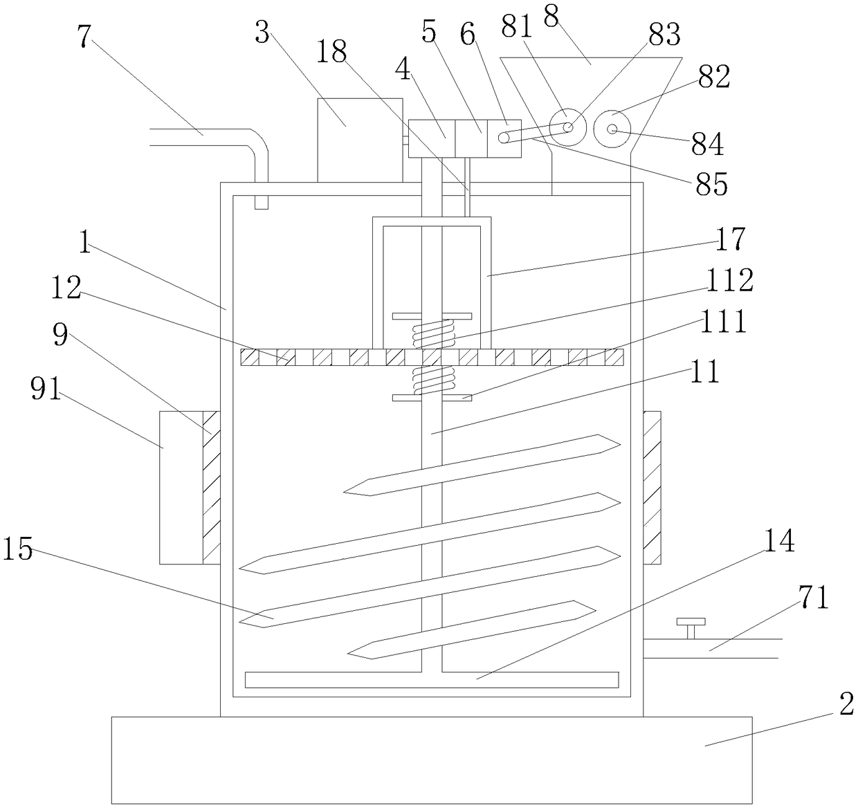
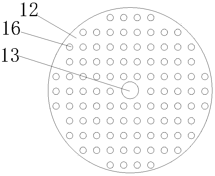
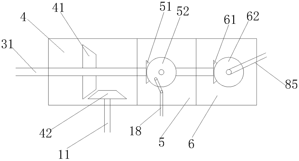
[0022] Such as figure 1 Shown: a slurry stirring device for a textile assembly line, comprising a cylindrical stirring drum 1 and a base 2. The stirring drum 1 is mounted on the base 2, and a motor 3 is installed on the upper side of the stirring drum 1. 3 through the rotating shaft 31 to respectively cooperate with the transmission of the gearbox I 4, the gearbox II 5 and the gearbox III6, the mixing drum 1 is provided with a mixing shaft 11 and a partition 12, and the upper side wall of the mixing drum 1 is provided with Shaft hole I, a shaft hole II 13 is provided in the center of the partition plate 12, the upper end of the stirring shaft 11 passes through the shaft hole I and is in a transmission fit with the gearbox I 4, and the middle part of the stirring shaft 11 passes through the shaft hole II 13, the lower end of the stirring shaft 11 is provided with a scraper bar 14, the center of the scraper bar 14 is welded perpendicularly to the lower end of the...


PUM


Abstract

The invention discloses a slurry stirring device for a spinning assembly line. The slurry stirring device comprises a cylindrical stirring cylinder and a base, the stirring cylinder is mounted on thebase, a motor is mounted on the upper side of the stirring cylinder, a stirring shaft and a separation plate are arranged in the stirring cylinder, and a scraping rod is arranged at the lower end of the stirring shaft. The scraping rod can prevent powdery pigment from sinking to the bottom, stirring blades can scratch the inner cylinder wall when works to rotate, so that the pigment cannot be deposited on the inner cylinder wall, the pigment is preliminarily smashed through a driving pressing roller and a driven pressing roller which are oppositely arranged, the pigment enters the stirring cylinder, and the slurry turning over upwards continuously can sufficiently make the pigment be uniformly mixed with water.

Description

technical field [0001] The invention relates to the field of textile technology, in particular to a slurry stirring device for a textile assembly line. Background technique [0002] In the textile industry, it is necessary to use dyes of different colors to dye the spun yarn into various colors. The dye is originally a block structure, which needs to be added to water and stirred to color. , a general term for all natural and synthetic high molecular polymers with viscous effect. They can be starch, carboxymethylcellulose, hydroxymethylcellulose, locust bean gum, sodium alginate, and the like. The current mixing tank only uses the stirring paddle for stirring. Such a mixing tank cannot effectively stir the dye fully, resulting in uneven dyeing and poor coloring, and the bottom and inner wall of the mixing tank tend to accumulate part of the dye during the stirring process. There is no better stirring, resulting in waste of resources. [0003] In addition, during the stirr...

Claims


Application Information

Patent Timeline
IPC IPC(8): B01F7/16B01F7/18B01F7/24B01F11/00B01F15/00B01F15/02B01F3/20B01F1/00B02C4/02B01F23/70
CPCB02C4/02B01F21/30B01F21/10B01F23/70B01F27/1921B01F27/92B01F27/80B01F31/00B01F35/123B01F27/90B01F35/71B01F2101/30
Inventor 喻英余琴李丽丽王留留楚肖肖范桂梅
Owner 安徽职业技术学院
Why Eureka
Try Eureka