
Photonic suspension gyroscope based on double-beam optical trap system

An optical trap system and double beam technology are applied in the fields of inertial measurement technology and optical engineering to achieve the effect of improving service life, overcoming influence and simple structure

Active Publication Date: 2018-12-21
NAT UNIV OF DEFENSE TECH
View PDF2 Cites 8 Cited by
  • Summary
  • Abstract
  • Description
  • Claims
  • Application Information

AI Technical Summary

Problems solved by technology

The device and method for measuring the deflection angle of the photonic levitation gyroscope using linear polarized light have not been reported yet

Method used


Image

  • Photonic suspension gyroscope based on double-beam optical trap system
  • Photonic suspension gyroscope based on double-beam optical trap system

Examples


Embodiment Construction

[0018] An embodiment of the present invention will be described in detail below in conjunction with the accompanying drawings, but the protection scope of the present invention should not be limited thereby;

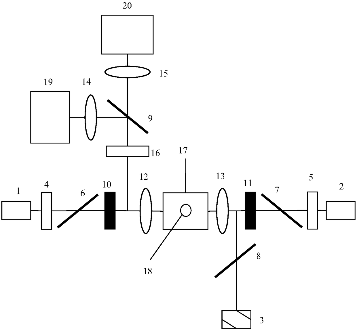
[0019] Such as figure 1 Shown: the device of the photonic levitation gyro, including No. 1 laser 1, No. 2 laser 2 and No. 3 laser 3, No. 1 half-wave plate 4, No. 2 half-wave plate 5, No. 1 polarization beam splitter 6, No. 2 polarizer Beam splitter 7, No. 3 polarizing beam splitter 8, No. 4 polarizing beam splitter 9, No. 1 λ / 4 slide 10, No. 2 λ / 4 slide 11, No. 1 lens 12, No. 2 lens 13, No. 3 No. lens 14, No. 4 lens 15, optical filter 16, vacuum chamber 17, microsphere 18, No. 1 photodetector 19, No. 2 photodetector 20, microsphere is birefringence microsphere, adopts jet or other ways to It is placed in a vacuum chamber.

[0020] Example of implementation of the present invention: Three lasers are selected as light sources for the three incident laser beams: No. 1 las...


PUM


Abstract

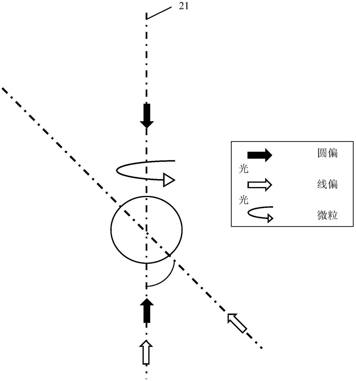
The invention relates to a photonic suspension gyroscope based on a double-beam optical trap system. A half-wave plate, a polarization beam splitter and a lambda / 4 slide are utilized to modulate lightoutput by a laser into two beams of circularly polarized light with the same light intensity, wherein the circularly polarized light is focused and input into a vacuum chamber through a lens. A corresponding relation exists between the light intensity detected by two photoelectric detectors and an included angle alpha of linearly polarized light and the maximum inertia main axis, wherein the ratio of the light intensity of e light to the light intensity of the o light is tan 2 alpha, namely, a deflection angle alpha can be obtained through the measured light intensity, so that the deflectionangle of the photonic suspension gyroscope can be determined. The device has no mechanical contact, so that influence of a supporting shaft on the precision of the whole system is overcome, the errorcaused by frictional resistance between the supporting shaft and a rotor is avoided, the service life of the system is prolonged, and relatively high precision can be achieved.

Description

technical field [0001] The invention relates to a photon suspension gyroscope based on a double-beam optical trap system, belonging to the fields of inertial measurement technology and optical engineering. Background technique [0002] The inertial navigation system is an autonomous track-returning navigation system that uses inertial sensitive devices, reference directions, and initial position and velocity information to determine the orientation and velocity of the carrier. The inertial navigation system has the advantages of autonomy, concealment, real-time, all-weather, etc., so it has been widely used in the navigation, guidance, positioning and stability control of various carriers. As an important part of the inertial navigation system, the gyroscope has been widely used in aviation, aerospace, navigation, surveying and other fields. [0003] With the development of science and technology, people have found that various physical phenomena can be used to detect the r...

Claims


Application Information

Patent Timeline
Patent Type & Authority Applications(China)
IPC IPC(8): G01C19/06G01C19/18
CPCG01C19/06G01C19/18
Inventor 肖光宗韩翔邓丹陈鑫麟杨开勇
Owner NAT UNIV OF DEFENSE TECH
Learn More