A DC/DC converter maximum inductor current sharing control method

An inductive current, converter technology, applied in the direction of converting DC power input to DC power output, control/regulation systems, instruments, etc., can solve the problems of system current sharing failure, system output interruption, reliability instability, etc. Dynamic performance, the effect of simplifying the design

Active Publication Date: 2018-12-21
HARBIN ENG UNIV
View PDF10 Cites 12 Cited by
  • Summary
  • Abstract
  • Description
  • Claims
  • Application Information

AI Technical Summary

Problems solved by technology

[0006] a. The hardware current sharing control method has high cost and unstable reliability. It is easy to cause the failure of the entire system current sharing due to a single point failure, and even cause the system output to be interrupted. The current sharing effect is greatly affected by electronic components;
[0007] b. The general software current sharing control method cannot adjust the adjustment step size in real time according to the output feedback current and voltage. If the adjustment step size is too small, the current sharing speed will be slow. flow fluctuation

Method used


Image

  • A DC/DC converter maximum inductor current sharing control method
  • A DC/DC converter maximum inductor current sharing control method
  • A DC/DC converter maximum inductor current sharing control method

Examples


Embodiment Construction

[0044] In order to make the above-mentioned purposes, features and advantages of the present invention more obvious and understandable, the present invention will be further described below in conjunction with the accompanying drawings:

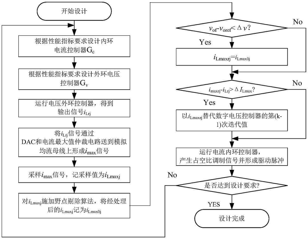
[0045] figure 1 It is a flow chart of a DC / DC converter maximum inductor current sharing control method;

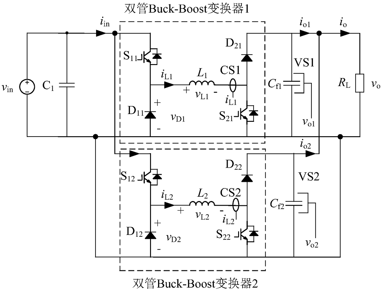
[0046] figure 2 It is a schematic diagram of parallel connection of two double-tube Buck-Boost converters used for example in the present invention;

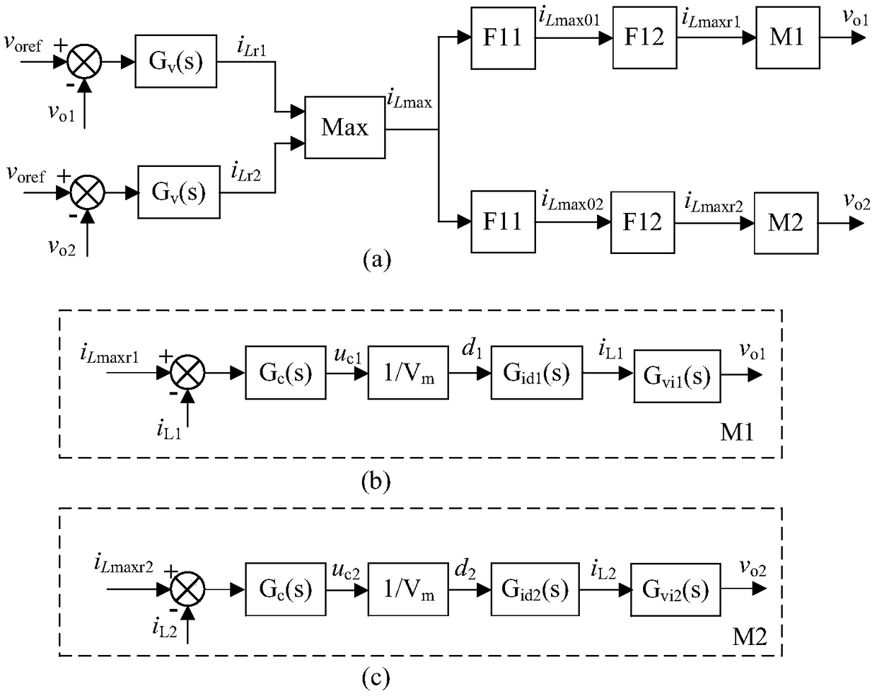
[0047] image 3 It is a schematic diagram of the control structure of the method for controlling the maximum inductor current sharing in the present invention.

[0048] Technical scheme of the present invention is realized like this:

[0049] figure 2 In , two dual-tube Buck-Boost converters are connected in parallel at the input and output. The dual-tube Buck-Boost converter itself is a mature circuit structure, so it will not be repeated here. In the figure, CS1 and CS2 are resp...


PUM


Abstract

The invention relates to the technical field of power electronics, in particular to a maximum inductor current sharing control method of a DC/DC converter. The inductor current command signal output by the voltage controller of each module is sent to the analog current sharing bus through the digital-to-analog converter DAC and the maximum arbitration circuit on the control board, so that the maximum value imax of the inductor current command of each module is obtained on the current sharing bus. Then each module resamples the imax signal on the current sharing bus, and processes the sampled signal as the inductor current command signal of the inductor current inner loop of the module. Compared with the current-sharing control loop based on output current, which uses the reference value ofoutput regulated voltage of current-sharing controller to realize output current equalization between modules, the method simplifies the design of the control system, significantly improves the dynamic performance of the current sharing control, ensures the dynamic control performance of the current sharing, and improves the balance of the output current of each module in the dynamic process.

Description

technical field [0001] The invention relates to the technical field of power electronics, in particular to a method for controlling the maximum inductance current sharing control of a DC / DC converter. Background technique [0002] The power supply system is the heart of the power electronic system. A stable and reliable power supply system is the key to ensure the safe and reliable operation of the power electronic system. Cause circuit interruption, power electronic system paralysis, resulting in great economic and social loss. Therefore, the power electronic power supply system occupies a very important position. [0003] In the field of power electronic power supply / converter systems, the capacity of the power supply system is usually increased by using multiple modules in parallel, and the reliability of the system is improved. In the power supply system that requires fast response, such as X-ray machine power supply, welding power supply or pulse power supply system, ...

Claims


Application Information

Patent Timeline
Patent Type & Authority Applications(China)
IPC IPC(8): H02M3/158H02M1/44
CPCH02M1/44H02M3/1584
Inventor 游江刘洪胜李晓旭王西贝
Owner HARBIN ENG UNIV
Why Eureka
Try Eureka