

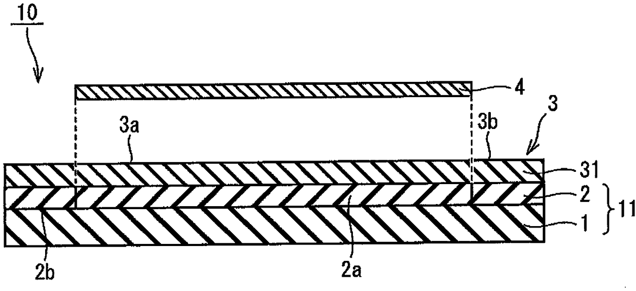
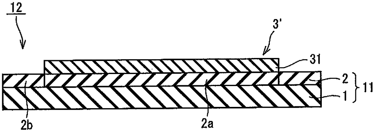
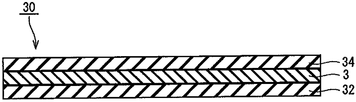
Thermal bonding sheet, thermal bonding sheet with dicing tape, bonded body production method, and power semiconductor device
A manufacturing method and cutting tape technology, applied in welding/cutting medium/material, semiconductor device, semiconductor/solid-state device manufacturing, etc., can solve problems such as thermal characteristics and reliability, and achieve the effect of cheap manufacturing
- Summary
- Abstract
- Description
- Claims
- Application Information
AI Technical Summary
Problems solved by technology
Method used
Image

Examples
Embodiment
[0169] Hereinafter, the present invention will be described in detail using examples, but the present invention is not limited to the following examples unless the gist is exceeded.
[0170] Components used in Examples will be described.
[0171] Copper particles A (average particle diameter 150nm, crystallite diameter size 30nm)
[0172] Copper particles B (average particle diameter 300nm, crystallite diameter size 30nm)
[0173] Pyrolytic binder A (polypropylene carbonate resin): QPAC40 manufactured by Empower, solid at 23°C
[0174] Low boiling point binder B (terpene alcohol-based binder (manufactured by Nippon Terpene Chemicals, Inc., TersolveMTPH))
[0175] Organic binder C (acrylic resin): MM-2002-1 manufactured by Fujikura Kasei Co., Ltd., solid at 23°C
[0176] Organic solvent A: methyl ethyl ketone (MEK)
[0177] [Production of heat bonding sheet]
[0178] According to the compounding ratio described in Table 1, each component and solvent described in Table 1 we...
PUM
| Property | Measurement | Unit |
|---|---|---|
| particle size | aaaaa | aaaaa |
| diameter | aaaaa | aaaaa |
| viscosity | aaaaa | aaaaa |
Abstract
Description
Claims
Application Information