
Metal powder extruding machine driving mechanism

A driving mechanism and metal powder technology, applied in presses, manufacturing tools, etc., can solve the problems of long cylinder stroke and low efficiency of box combination

Inactive Publication Date: 2018-12-25
芜湖市晨睿建材有限公司
View PDF8 Cites 0 Cited by
  • Summary
  • Abstract
  • Description
  • Claims
  • Application Information

AI Technical Summary

Problems solved by technology

[0004] The traditional extruder drive mechanism uses a long cylinder to squeeze the osmotic pressure box step by step, that is, the pressure plate at the end of the piston rod of the cylinder first contacts the nearest osmotic pressure box, and then the piston rod of the cylinder continues The elongation will make the first osmotic pressurization box contact the second osmotic pressurization box, and so on, to realize the combined operation of multiple osmotic pressurized boxes, the efficiency of the combined box is low, and the stroke of the cylinder is very long

Method used


Image

  • Metal powder extruding machine driving mechanism
  • Metal powder extruding machine driving mechanism
  • Metal powder extruding machine driving mechanism

Examples


Embodiment 1

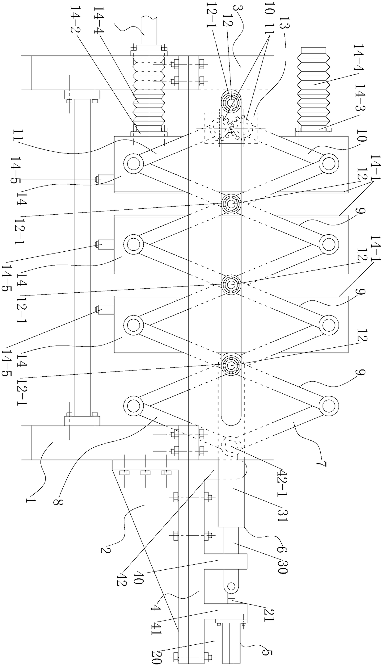
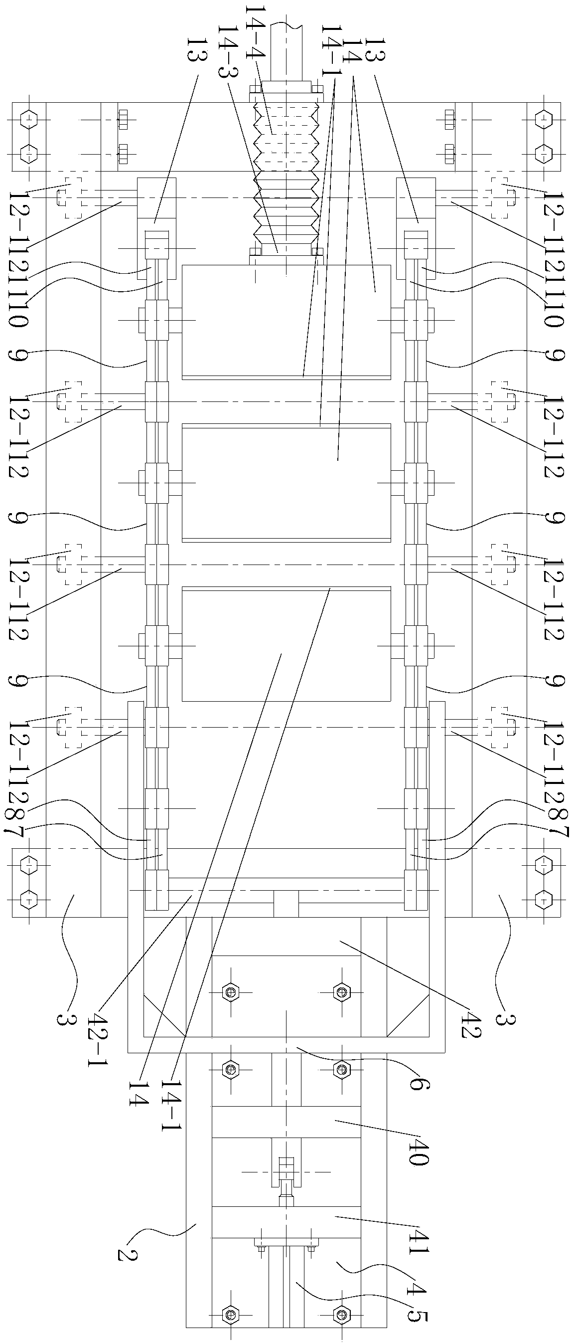
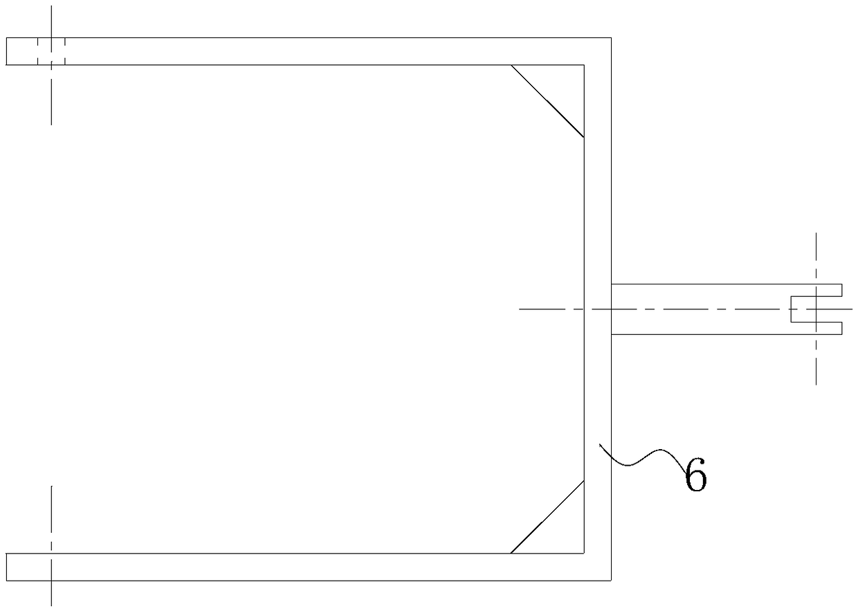
[0030] The driving mechanism of the metal powder extruder starts the hydraulic cylinder 5, and the piston rod of the hydraulic cylinder 5 shrinks, because the scissor lever group 9 is provided with multiple groups, which are respectively scissor lever one and scissor lever two from right to left. and scissor bar three, the left side of scissor bar one is hinged to the right side of scissor bar two, the left side of scissor bar two is hinged to the right side of scissor bar three, and the driving fork is mobile connected with guide seat 40, and The right end of the driving fork 6 is hinged with the piston rod output end of the hydraulic cylinder 5, the left end of the driving fork 6 is hinged with the middle part of the scissor rod through the steel shaft 12, one end of the connecting rod 7 is hinged with the hinge shaft 42-1, and the other end It is hinged with the right upper end of the scissor lever one, the one end of the connecting rod two is hinged with the hinge shaft 42-1,...

Embodiment 2

[0032] On the basis of Embodiment 1, the end of the steel shaft 12 is provided with a rolling bearing 12-1, and the rolling bearing 12-1 can roll in the long groove 30, ensuring the weight of the scissor bar set 9 and the osmosis pressurization box 14 support, while ensuring the linear movement of the osmotic pressurization box 14 opening and closing; the driving fork 6 is a "U"-shaped fork, which ensures the uniformity of symmetrical force; the outer edge of the osmotic pressurization box 14 is provided with a seal Circle 14-1, to avoid incomplete dehydration caused by leakage of high-pressure gas; the lower end of the leftmost osmotic pressurization box 14 is provided with an inlet flange 14-2, and the upper end is provided with an air inlet flange 14-3, Both the inlet flange 14-2 and the gas inlet flange 14-3 are provided with metal bellows 14-4, so that the osmosis pressurization box 14 can be opened and closed without affecting the connection of the material supply and the...

Embodiment 3

[0034] By lengthening the number of side plate beams 3 and scissor bars, the number of osmotic pressurization boxes 14 can be changed to achieve a change in width, which can meet ball mills with different capacities.


PUM


Abstract

The invention discloses a metal powder extruding machine driving mechanism. The metal powder extruding machine driving mechanism comprises a main bracket, an auxiliary bracket, lateral plate beams, aguide mounting bracket, a hydraulic cylinder, a driving fork, a first connecting rod, a second connecting rod, shearing fork rod sets, a third connecting rod, a fourth connecting rod, steel shafts, connecting pieces, and permeation pressurization boxes. The guide mounting bracket is connected with the auxiliary bracket. Long grooves are formed in the middle portions of the lateral plate beams. A guided seat is arranged at the middle of the guide mounting bracket. A rear mounting seat is arranged at the rear end of the guide mounting bracket. A front mounting seat is arranged at the front end of the guide mounting bracket. The front mounting seat is provided with a hinging shaft. The hydraulic cylinder is connected with the rear mounting seat. The shearing fork rod sets comprise a first shearing fork rod, a second shearing fork rod and a third shearing fork rod from right to left. Incomplete gears are arranged at the ends of the third connecting rod and the fourth connecting rod. The two incomplete gears are engaged. The middle portions of the first shearing fork rod, the second shearing fork rod and the third shearing fork rod are hinged by the steel shafts. Opening and closing operation of the multiple permeation pressurization boxes can be achieved by a short stroke of the driving mechanism, the box opening and closing efficiency is high, and the width can be adjusted based on ball mills with different capacities.

Description

technical field [0001] The invention belongs to the technical field of extruders, in particular, the invention relates to a driving mechanism of a metal powder extruder. Background technique [0002] The ball mill is the key equipment for crushing the material after it is crushed. It is widely used in cement, silicate products, new building materials 52555, refractory materials, chemical fertilizers, black and non-ferrous metal beneficiation, glass ceramics and other production industries, for dry or wet grinding of various ores and other grindable materials . [0003] Wet grinding is to pass water into the cylinder for grinding. In the process of metal grinding, wet grinding is often used. The metal powder after grinding needs to be dehydrated, and a metal powder extruder is required. [0004] The traditional extruder drive mechanism uses a long cylinder to squeeze the osmotic pressure box step by step, that is, the pressure plate at the end of the piston rod of the cylin...

Claims


Application Information

Patent Timeline
IPC IPC(8): B30B9/06B30B15/00
CPCB30B9/062B30B15/0052
Inventor 张世龙
Owner 芜湖市晨睿建材有限公司
Learn More