Laser quenching device and technology thereof

A laser quenching and process technology, applied in the direction of manufacturing tools, heat treatment equipment, furnaces, etc., can solve the problems of long heating and cooling process time, long heating and cooling time, low degree of automation, etc., to achieve short quenching time and process cycle Short, no effect of mechanical forces and tool wear

Pending Publication Date: 2018-12-25
深圳市艺盛科五金电子有限公司
View PDF0 Cites 2 Cited by
  • Summary
  • Abstract
  • Description
  • Claims
  • Application Information

AI Technical Summary

Problems solved by technology

[0003] 1. The efficiency is low, and it takes a long time to heat up and cool down;
[0004] 2. No energy saving, because the quenching furnace needs to be raised to a higher temperature, the consumption of electric energy is huge, the process of heating and cooling takes a long time and consumes a lot of energy;
[0005] 3. Unsafe, due to the high temperature of the quenching furnace, the operation should be extra careful;
[0006] 4. It is not environmentally friendly. After the temperature rise is completed, the probe needs to enter the anti-rust oil, which is easy to cause secondary pollution to the environment;
[0007] 5. The heat input is uncontrollable, and the product will have a large deformation, which will affect the yield rate;
[0008] 6. The production operation requires more labor and the degree of automation is not high

Method used


Image

  • Laser quenching device and technology thereof
  • Laser quenching device and technology thereof

Examples


Embodiment Construction

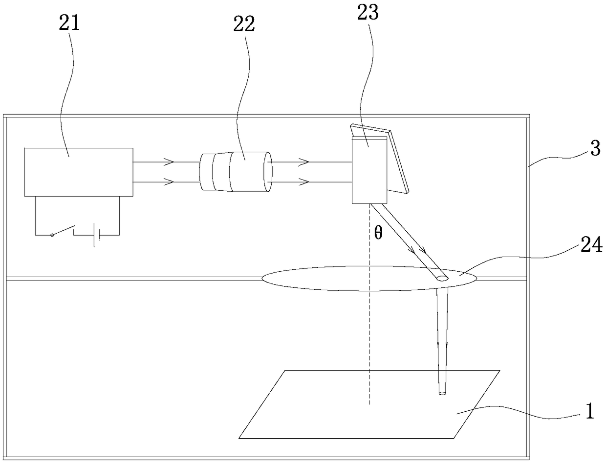
[0023] The specific embodiment of the present invention will be further described in detail below in conjunction with the accompanying drawings, and the probe is used as the workpiece.

[0024] Such as figure 1 As shown, the laser quenching device includes a frame 3, a workbench 1 and a laser assembly arranged on the frame 3, and the laser assembly is arranged above the workbench 1. The frame 3 includes a skeleton, a shell, and the workbench 1 and the laser assembly are arranged in the cavity of the shell; the frame 3 is provided with at least two compartments distributed vertically, and the laser assembly and the workbench 1 are arranged on different The workbench 1 is arranged on the lower floor, and the laser component is arranged on the upper floor. It also includes a controller, the laser 21 and the vibrating mirror 23 are both electrically connected to the controller, and the controller controls the on-off of the laser 21 and the action of the vibrating mirror 23 . The...


PUM


Abstract

The invention discloses a laser quenching device which comprises a working table and a laser assembly disposed above the working table, wherein the laser assembly comprises a laser, a beam expander, agalvanometer and an F-Theta lens arranged in sequence in a beam transmission direction. The multi-dimensional dynamic galvanometer ensures that light spots cannot be distorted within an effective range; the software control is accurate, the quenching depth can be precisely controlled, and the laser output energy, a scanning path and the like can be precisely controlled, so that an internal crystal structure is more refined, a hot deformation zone of a probe and the overall change are small, the product consistency and the yield rate are greatly improved, the hardness is increased by 15% to 20% compared with that of the conventional quenching, and the wear resistance can be increased by 3-4 times; no relatively long-term pretreatment and heating of the conventional method are required; theenergy consumption is reduced; laser-scanned probes do not need to be immersed in anti-rust oil, thereby reducing secondary pollution; and the laser quenching device is short in process cycle, high in production efficiency and low in cost, can be incorporated into a production line, and facilitates mass production.

Description

technical field [0001] The invention relates to the field of metal heat treatment, in particular to a laser quenching device and a laser quenching process for probes. Background technique [0002] During the heat treatment of the probe, in order to increase the hardness of the product, a quenching process is required. The quenching link in the current probe production is handled by the traditional method: wrap the product with tin foil (the purpose of wrapping is to prevent the product from oxidizing), and then put it in a quenching furnace and heat it to more than 1,000 degrees (this heating takes a certain time ), then keep the high temperature for a few minutes, then remove the tinfoil, pour the product into the anti-rust oil for cooling (the cooling process takes a certain period of time), take it out after the product cools to room temperature, and then put it in the vacuum tempering furnace for a few minutes Hours (the temperature of the tempering furnace is about 300...

Claims


Application Information

Patent Timeline
Patent Type & Authority Applications(China)
IPC IPC(8): C21D1/09C21D9/26
CPCC21D1/09C21D9/26
Inventor 王锐谭国甫王雪彬忠民刘靖周飚
Owner 深圳市艺盛科五金电子有限公司
Why Eureka
Try Eureka