
A microfocal X-ray tube based on field emission of carbon nanotubes

An X-ray tube, carbon nanotube technology

Inactive Publication Date: 2018-12-25
广州市昊志影像科技有限公司
View PDF9 Cites 3 Cited by
  • Summary
  • Abstract
  • Description
  • Claims
  • Application Information

AI Technical Summary

Problems solved by technology

However, there are some fatal problems in growing carbon nanotube field emission arrays by CVD method: 1) the distance between carbon nanotubes is very dense, and the electric field shielding effect is very serious; 2) the electrical contact and adhesion between carbon nanotubes and the substrate are very poor , resulting in serious heating due to the very large contact resistance with the substrate when emitting at high current density, and then burning
3) The consistency of the growth of large-area carbon nanotubes is not good, resulting in uneven emission of different carbon nanotubes during current emission, and local carbon nanotubes are often overheated and burned
Existing micro-focus X-ray tubes have certain limitations: 1) It is very difficult for traditional thermal emission cathodes to achieve micron-scale effective emission surfaces. In the application of micro-focus, the effective focal spot of X-rays is required to be very small, adding Due to the mechanism of electron emission on the upper thermal emission cathode, the emission angle of the electron beam is very large. To achieve the purpose of micro-focus, it is necessary to match a complex focusing lens (such as a multi-level focusing lens), which makes the structure of the whole tube complicated. , which makes the production cost of the thermal emission cathode applied to the micro-focus X-ray tube very high, and the emission cathode is very easy to damage
2) The field emission cathode materials currently reported have a relatively small emission current density. In order to achieve the expected emission current, the corresponding emission cathode area becomes larger, and it is very difficult to converge into a micro focus

Method used


Image

  • A microfocal X-ray tube based on field emission of carbon nanotubes
  • A microfocal X-ray tube based on field emission of carbon nanotubes
  • A microfocal X-ray tube based on field emission of carbon nanotubes

Examples


Embodiment 1

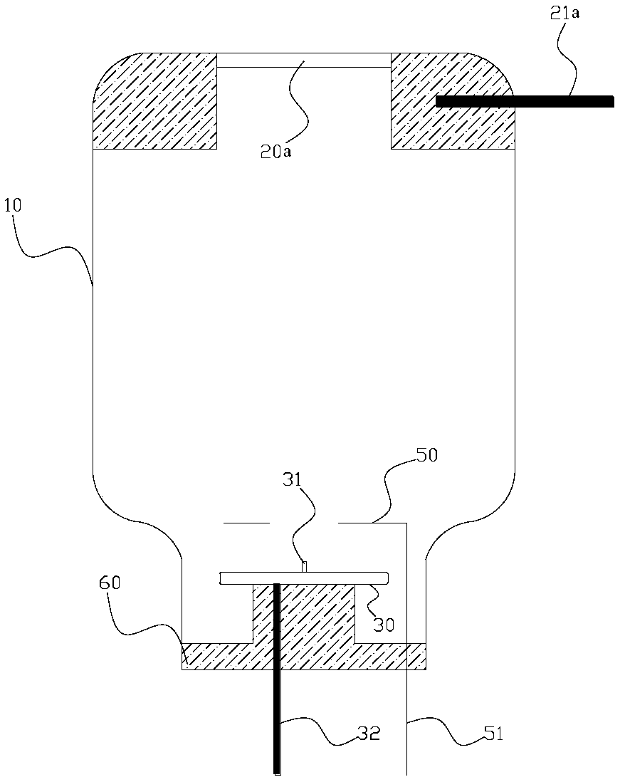
[0053] Embodiment one adopts figure 1 Described end window structure. Please refer to figure 1 As shown, a micro-focus X-ray tube based on carbon nanotube field emission includes a vacuum vessel 10 and an anode target 20a installed in the vacuum vessel 10 and an electron gun, and the electron gun includes an emission cathode and a control grid 50, The emission cathode and the anode target 20a are respectively installed at opposite ends of the vacuum vessel 10, the control grid 50 is installed between the emission cathode and the anode target 20a, and the emission cathode includes the emission cathode substrate 30 and is vertically grown on The carbon nanotube microbundle 31 extending toward the anode target 20a on the emission cathode substrate 30, the carbon nanotube microbundle 31 is a single bundle of carbon nanotubes or a carbon nanotube array with a diameter of 0.1-500 μm, that is, if it is For a single bundle of carbon nanotubes, the diameter of the single bundle of ca...

Embodiment 2

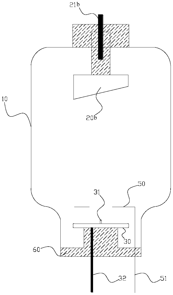
[0069] The difference between the second embodiment and the first embodiment is that the installation position of the anode target 20b is different. The first embodiment adopts the end window structure, while the second embodiment adopts the side window structure. Please refer to figure 2 As shown, a micro-focus X-ray tube based on carbon nanotube field emission includes a vacuum vessel 10 and an anode target 20b installed in the vacuum vessel 10 and an electron gun, and the electron gun includes an emission cathode and a control grid 50, The emission cathode and the anode target 20b are respectively installed at opposite ends of the vacuum container 10, the control grid 50 is installed between the emission cathode and the anode target 20b, and the emission cathode includes the emission cathode substrate 30 and is vertically grown on The emitting carbon nanotube microbundle 31 on the cathode substrate 30 and extending toward the anode target 20b, the carbon nanotube microbund...

Embodiment 3

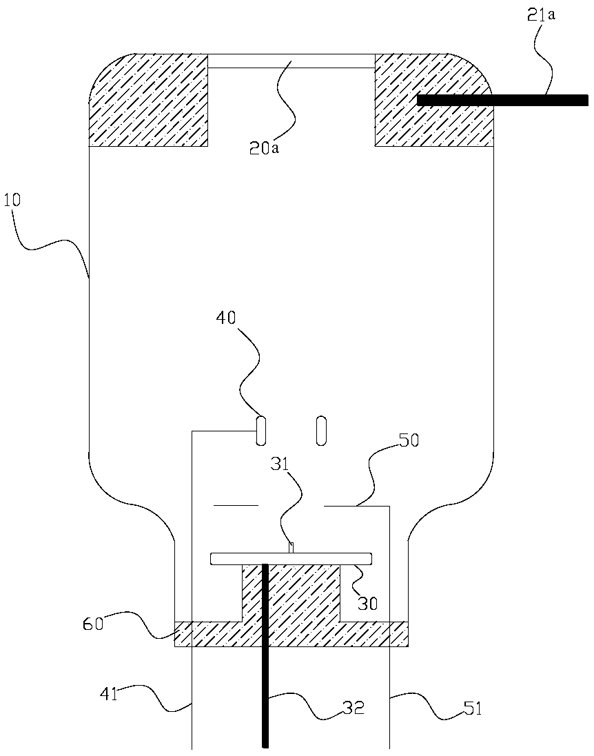
[0072] Embodiment three adopts image 3 Described X-ray tube end window structure. Please refer to image 3 As shown, a micro-focus X-ray tube based on carbon nanotube field emission includes a vacuum vessel and an anode target 20a installed in the vacuum vessel 10 and an electron gun, and the electron gun includes an emission cathode and a control grid 50, so The emitting cathode and the anode target 20a are respectively installed at opposite ends of the vacuum container 10, the control grid 50 is installed between the emitting cathode and the anode target 20a, and the emitting cathode includes the emitting cathode substrate 30 and is vertically grown on the The carbon nanotube microbundle 31 that is emitted on the cathode substrate 30 and extends toward the anode target 20a, the carbon nanotube microbundle 31 is a single bundle of carbon nanotubes or a carbon nanotube array with a diameter of 0.1-500 μm, that is, if it is a single If it is a bundle of carbon nanotubes, the...


PUM


Abstract

The invention discloses a micro-focus X-ray tube based on field emission of carbon nanotube, which comprises a vacuum container, an anode target mounted in the vacuum container and an electron gun, The electron gun comprises an emitter cathode and a control grid, wherein the emitter cathode and the anode target are respectively arranged at opposite ends in a vacuum vessel, the control grid is arranged between the emitter cathode and the anode target, and the emitter cathode comprises an emitter cathode substrate and a carbon nanotube microbeam grown on the emitter cathode substrate perpendicularly and extending toward the anode target; The anode target, the emitting cathode and the control grid are respectively led out of the vacuum vessel through the anode target electrode, the emitting cathode electrode and the control grid electrode. The invention adopts the carbon nanotube microbeam perpendicular to the emitter cathode substrate as the field emission basic unit, has very high fieldemission current density and very high emission current stability, and overcomes the phenomenon of local overheating burnout of the traditional field emission cathode.

Description

technical field [0001] The invention relates to the technical field of X-ray tubes, in particular to micro-focus X-ray tubes that generate X-rays based on carbon nanotube field emission as an electron source. Background technique [0002] X-ray tube is a device that can generate X-rays. X-rays play a pivotal role in scientific research and technical applications such as material crystal analysis, molecular reaction dynamics research, industrial non-destructive testing, biological science and medical imaging, diagnosis and treatment. . X-ray tubes are the core components of X-ray imaging, testing and CT systems, and the performance of X-ray tubes directly determines the overall performance of the imaging system. The traditional X-ray tube adopts the thermal emission cathode structure, and needs to heat the emission cathode filament to 700-1600°C to work normally. At this time, the electrons on the surface of the emission cathode material have obtained enough energy to reach ...

Claims


Application Information

Patent Timeline
Patent Type & Authority Applications(China)
IPC IPC(8): H01J35/24H01J35/06
CPCH01J35/06H01J35/24
Inventor 汤秀清陈泽祥
Owner 广州市昊志影像科技有限公司
Learn More