
High-temperature annealing method of low-temperature and high-magnetic-induction oriented silicon steel

A technology of high magnetic induction orientation and high temperature annealing, applied in furnace types, furnaces, heat treatment furnaces, etc., can solve problems such as excessive oxidation, affecting steel coils, affecting the quality of finished products, etc., to reduce temperature differences, improve quality uniformity, weaken The effect of heat radiation

Active Publication Date: 2019-01-01
SHOUGANG ZHIXIN QIAN AN ELECTROMAGNETIC MATERIALS CO LTD +1
View PDF4 Cites 5 Cited by
  • Summary
  • Abstract
  • Description
  • Claims
  • Application Information

AI Technical Summary

Problems solved by technology

[0005] In the prior art, due to the heavy weight of the steel coil, there must be a temperature difference between the inner and outer rings of the steel coil and the width direction of the steel coil during the high-temperature annealing process. When the temperature exceeds 800°C, the dew point of the atmosphere in the inner cover will still be at a relatively high level. At this time, the high dew point atmosphere will in turn affect the oxide film on the surface of the upper and lower outer rings of the steel coil, making it excessively oxidized, causing local dew crystal defects and worsening The quality of the bottom layer of hundreds of meters in the outer ring affects the quality of finished products
[0006] In addition, because the lower end of the steel coil is in contact with the bottom plate of the steel coil, due to the difference in thermal expansion coefficient between the two, the lower end of the steel coil is prone to bottom deformation defects during the heating and cooling process, which will also affect the quality of the finished product

Method used


Image

  • High-temperature annealing method of low-temperature and high-magnetic-induction oriented silicon steel
  • High-temperature annealing method of low-temperature and high-magnetic-induction oriented silicon steel
  • High-temperature annealing method of low-temperature and high-magnetic-induction oriented silicon steel

Examples


Embodiment Construction

[0033] The following will clearly and completely describe the technical solutions in the embodiments of the present invention with reference to the accompanying drawings in the embodiments of the present invention. Obviously, the described embodiments are only some, not all, embodiments of the present invention. Based on the embodiments of the present invention, all other embodiments obtained by persons of ordinary skill in the art without making creative efforts belong to the protection scope of the present invention.

[0034] The embodiment of the present invention provides a high temperature annealing method for low temperature high magnetic induction oriented silicon steel, which is suitable for high temperature annealing of low temperature high magnetic induction oriented silicon steel.

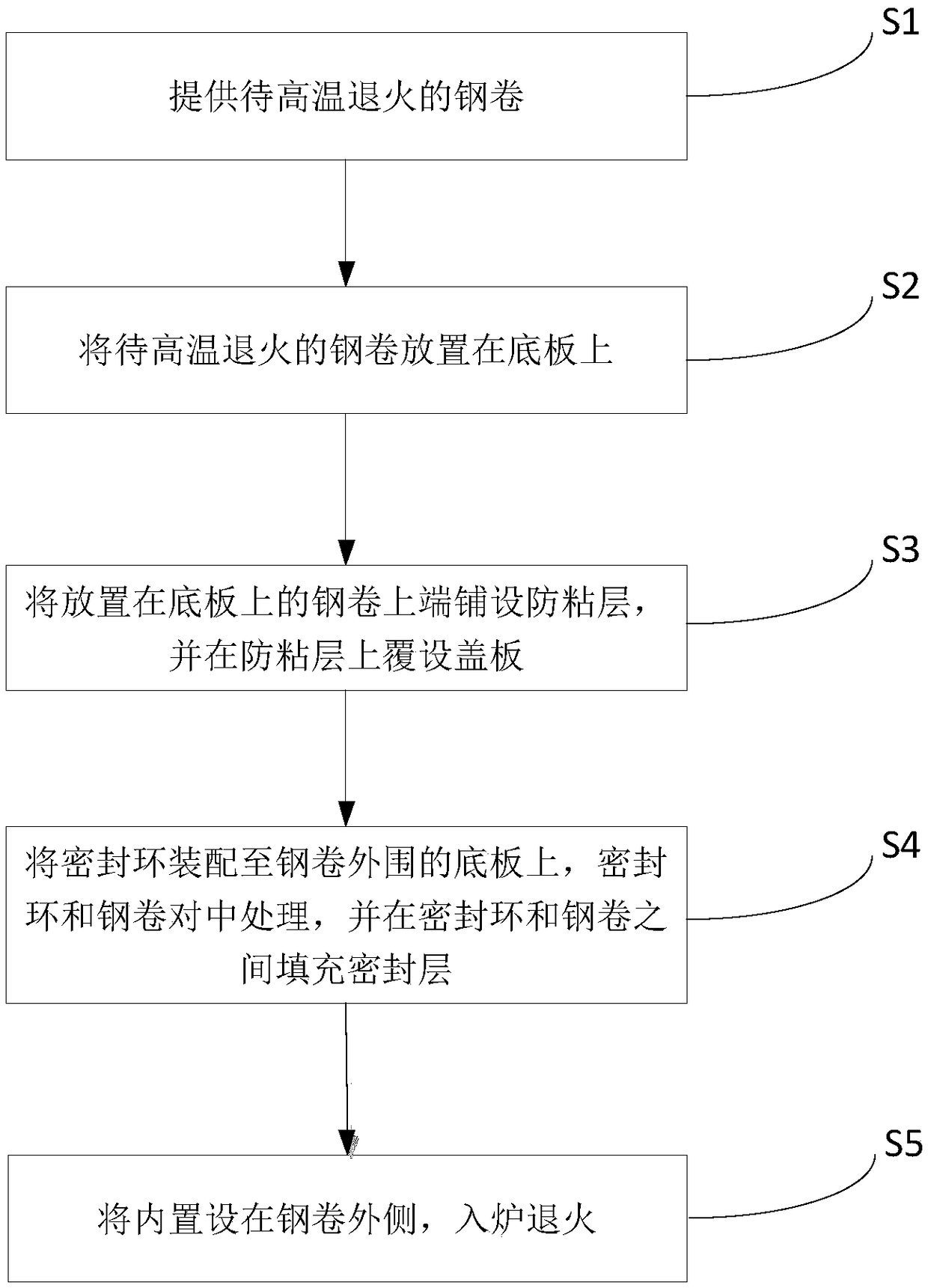
[0035] figure 1 It is a process flow chart of a high-temperature annealing method for low-temperature high-magnetic-inductive grain-oriented silicon steel according to an embodiment of t...


PUM


Abstract

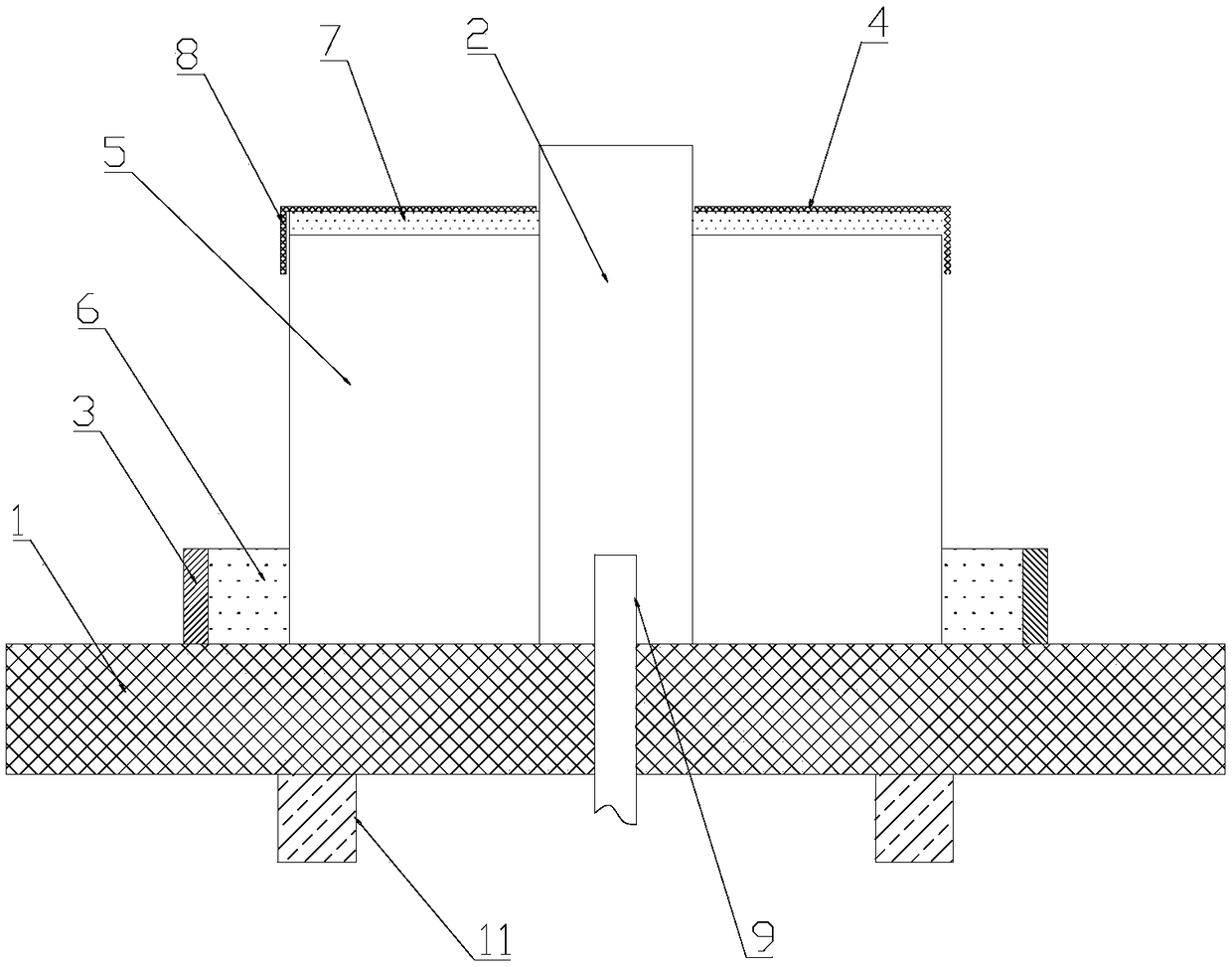
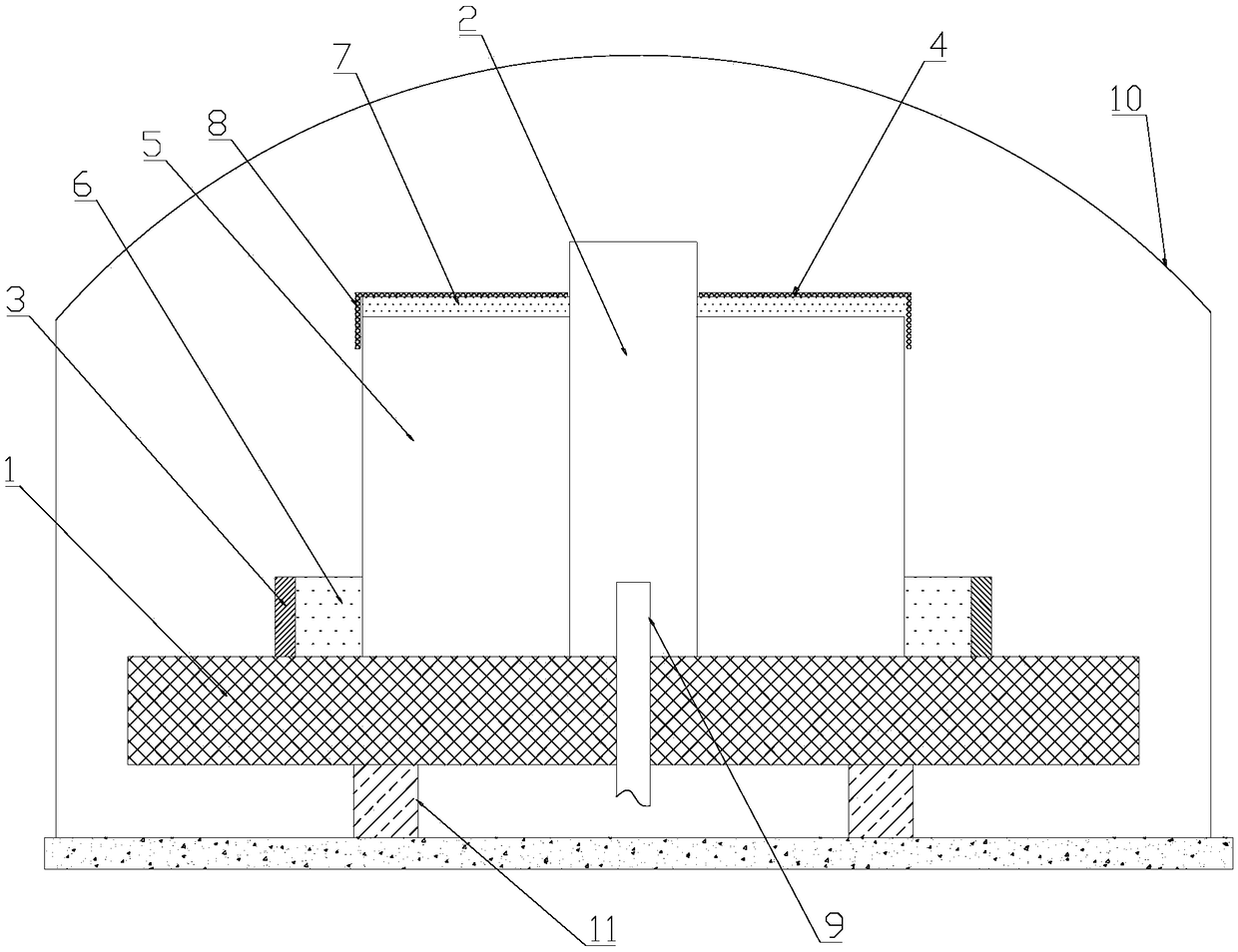
The invention belongs to the technical field of manufacturing of oriented silicon steel, and in particular relates to a high-temperature annealing method of low-temperature and high-magnetic-inductionoriented silicon steel. The method comprises the following steps: providing a steel coil to be annealed at a high temperature; placing the steel coil to be annealed at the high temperature on a bottom plate; laying an anti-adhesion layer on the upper end of the steel coil placed on the bottom plate, and covering the anti-adhesion layer with a cover plate; assembling a sealing ring on the bottom plate at the periphery of the steel coil, centering the sealing ring and the steel coil, and filling the part between the sealing ring and the steel coil with a sealing layer; then, additionally arranging an inner cover on the steel coil, putting in a furnace and annealing. The method can improve the quality of the steel coil.

Description

technical field [0001] The invention belongs to the technical field of oriented silicon steel manufacturing, and in particular relates to a high-temperature annealing method for oriented silicon steel with low temperature and high magnetic induction. Background technique [0002] The production process of low temperature and high magnetic induction oriented silicon steel in the cold rolling area is as follows: hot rolled coil → normalized pickling line → rolling line → decarburization annealing line → high temperature annealing line → stretch tempering line. Oriented silicon steel is formed with SiO on the surface of the steel plate in the decarburization annealing unit 2 , FeO, Fe 2 o 3 etc. as the main component of the oxide layer, and coated with MgO as the main component of the release agent. During high temperature annealing, the surface oxide reacts with the release agent to form a glass film. [0003] The release agent needs to be prepared into a slurry before coa...

Claims


Application Information

Patent Timeline
IPC IPC(8): C21D1/26C21D1/70C21D9/52C21D1/74
CPCC21D1/26C21D1/70C21D1/74C21D9/52
Inventor 王现辉贺小国龚坚张广治赵松山司良英黎先浩滕仁昊
Owner SHOUGANG ZHIXIN QIAN AN ELECTROMAGNETIC MATERIALS CO LTD
Learn More