Preparation method of fiber-enhanced high temperature alloy composite material via in-situ generation

A fiber-reinforced, composite material technology, applied in the field of in-situ generation of fiber-reinforced superalloy composite materials

Active Publication Date: 2019-01-01
UNIV OF SCI & TECH BEIJING
View PDF12 Cites 3 Cited by
  • Summary
  • Abstract
  • Description
  • Claims
  • Application Information

AI Technical Summary

Problems solved by technology

Make the reinforcing fiber grow directly from the superalloy matrix to obtain a composite material with a st

Method used


Image

  • Preparation method of fiber-enhanced high temperature alloy composite material via in-situ generation
  • Preparation method of fiber-enhanced high temperature alloy composite material via in-situ generation

Examples


preparation example Construction

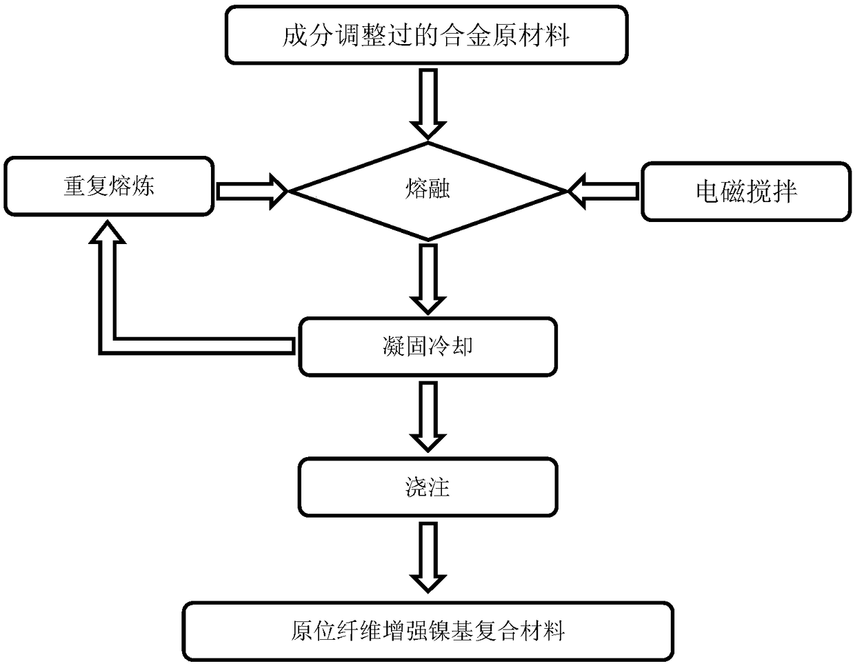
[0026] figure 1 A flowchart showing a method for preparing a fiber-reinforced superalloy-based composite material according to the present invention. Specifically, the following steps are included:

[0027] Step 101, put the composition-adjusted raw material composition of the alloy material into the crucible of the vacuum electric arc furnace according to the proportion. The raw material composition and proportion of the alloy material in step 101 are: chromium element, accounting for 25-40 at.% of the total number of atoms; carbon element, accounting for 15-30 at.% of the total number of atoms; 5at.%, nickel element content is the balance. Wherein, the purity of the nickel, chromium, carbon and titanium is not lower than 98%. Experiments have proved that when the carbon element accounts for 15-30 at.% of the total atomic number, the interface of the superalloy-based composite material formed is the most stable.

[0028] Step 102, melt the raw material components to a liq...

Embodiment 1

[0032] (1) 22g alloy material raw material (composition is 30at.% chromium, 15at.% carbon, 5at.% titanium, the balance is nickel, wherein, the purity of described nickel, chromium, carbon, titanium is 99%) is put into Vacuum non-consumable electric arc furnace crucible.

[0033] (2) Under the protection condition of argon gas with a pressure of 0.02MPa, the raw material components were smelted to a liquid state by vacuum arc melting, and the melt was stirred by an electromagnetic stirring device at the same time. The electromagnetic stirring current value was 1A, and the stirring time was 6 minutes.

[0034] (3) After the melt was solidified and cooled, the melting was repeated six times, and poured into a metal mold to obtain an in-situ fiber-reinforced nickel-based composite material.

Embodiment 2

[0036] (1) 22g alloy material raw material (composition is 30at.% chromium, 30at.% carbon, 5at.% titanium, the balance is nickel, wherein, the purity of described nickel, chromium, carbon, titanium is 99%) is put into Vacuum non-consumable electric arc furnace crucible.

[0037] (2) Under the protection condition of argon gas with a pressure of 0.02MPa, the raw material components were smelted to a liquid state by vacuum arc melting, and the melt was stirred by an electromagnetic stirring device at the same time. The electromagnetic stirring current value was 1A, and the stirring time was 6 minutes.

[0038] (3) After the melt was solidified and cooled, the melting was repeated six times, and poured into a metal mold to obtain an in-situ fiber-reinforced nickel-based composite material.

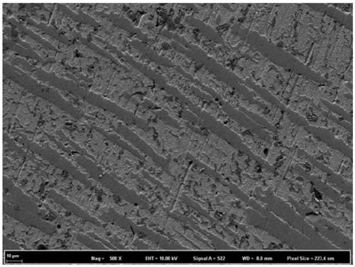
[0039] In the composites prepared in this way, there are a large amount of M 7 C 3 (M is mainly Cr) crystal fiber. m 7 C 3 The phase is a complex hexagonal structure, which can form long...


PUM

PropertyMeasurementUnit
Hardnessaaaaaaaaaa

Abstract

The invention discloses a preparation method of a fiber-enhanced high temperature alloy composite material via in-situ generation, and belongs to the technical field of preparation of materials. The preparation method comprises the following steps of preparing the materials according to typical high temperature alloy components, and increasing the content of carbon element in proportioning, so asto increase the content of carbon; smelting by a vacuum electric arc furnace, so as to form fiber-shaped carbide, thereby obtaining the fiber-enhanced high temperature alloy composite material via in-situ generation. The preparation method has the advantage that the enhancing fibers directly grow in a high temperature alloy matrix, so as to obtain the composite material with a stable interface, thereby solving the problem of poor interface compatibility of the fiber-enhanced high temperature alloy composite material.

Description

technical field [0001] The invention belongs to the technical field of material preparation, and in particular relates to a method for in-situ generation of fiber-reinforced superalloy composite materials. Background technique [0002] The biggest problem that needs to be solved in fiber reinforced superalloy composite materials is the interfacial compatibility problem. In order to solve the problem of interface reaction at this stage, the means of interface coating is generally used to block, so as to prevent the occurrence of reaction. However, during the development of fiber-reinforced superalloy composite materials, coating materials with good barrier effect and stable performance have not been obtained; and the way of coating barrier is dangerous. Once the coating is damaged, reactions will continue to occur, which is extremely risky. high. Contents of the invention [0003] In order to solve the above problems, the present invention provides a method for preparing ...

Claims


Application Information

Patent Timeline
IPC IPC(8): C22C47/00C22C49/02C22C49/14C22C101/10
CPCC22C47/00C22C49/02C22C49/14
Inventor 江河李昕王法董建新
Owner UNIV OF SCI & TECH BEIJING
Why Eureka
Try Eureka