
Measuring method of laser beam quality factor M2 and measuring device thereof

A technology of beam quality and measurement method, which is applied in the field of lasers, can solve the problems of affecting measurement efficiency and measurement accuracy, taking a long time, and heavy workload, and achieves the effects of fast and simple measurement, compact structure, and cost saving

Active Publication Date: 2019-01-01
索镭德激光科技(苏州)有限公司
View PDF8 Cites 4 Cited by
  • Summary
  • Abstract
  • Description
  • Claims
  • Application Information

AI Technical Summary

Problems solved by technology

[0008] The measurement method of the M2 factor of the laser beam quality in the prior art, after the beam is focused through the lens, the front and rear sections of the beam waist of the laser beam are measured by using CCD (Charge Coupled Device, charge coupled device image sensor), trepanning or scanning slit and other components. The spot diameter of several points within the distance, and then use the method of hyperbolic fitting to obtain the M2 factor; while using the method of hyperbolic fitting to measure the M2 factor, it is necessary to measure the spot diameter of multiple points within the Rayleigh range, in order to obtain a better The fitting accuracy usually needs to measure more than ten points. It takes a long time to measure the spot diameter of different positions so many times and increases the workload. As a result, it cannot be applied to the situation where M2 needs to be measured quickly in the engineering field. , problems affecting measurement efficiency and measurement accuracy

Method used


Image

  • Measuring method of laser beam quality factor M2 and measuring device thereof
  • Measuring method of laser beam quality factor M2 and measuring device thereof
  • Measuring method of laser beam quality factor M2 and measuring device thereof

Examples


Embodiment 1

[0045] A kind of measurement method of laser beam quality factor M2, see figure 1 , including the following steps:

[0046] Focus the Gaussian beam of the laser to be tested through a positive lens L1 with a focal length of f1;

[0047] Move the CCD back and forth to find the minimum spot position of the focused Gaussian beam;

[0048] Measure and record the minimum spot diameter d1 at the minimum spot position to obtain the beam waist diameter d=d of the Gaussian beam 1 ;

[0049] A focusing lens L2 with a focal length of f2 is arranged behind the focused Gaussian beam, and then the focal spot diameter d2 is measured at the focal plane position of the focusing lens L2, then the divergence angle θ of the Gaussian beam is passed by the following formula Get:

[0050]

[0051] Then the M2 factor can be obtained by the following formula:

[0052]

[0053] Among them, λ is the wavelength of the Gaussian beam of the laser to be tested, and π is the circumference ratio. ...

Embodiment 2

[0056] A method for measuring the laser beam quality factor M2 is similar to Embodiment 1, except that the positive lens L1 is a plano-convex lens; the plane of the positive lens L1 is the incident surface of the light beam, and the convex surface is the surface of the light beam. exit surface.

[0057] In this way, the positive lens L1 is a plano-convex lens, and the distance from the convex surface to the focal point is equal to the back focal length BFL (Back Focus Length, back focal length) and the effective focal length EFL (Effective Focus Length), which is convenient for handling.

[0058] In another specific embodiment, the diameter of the positive lens L1 is larger than the diameter of the incident light spot of the laser.

[0059] In another specific embodiment, the focusing lens L2 is a plano-convex lens, the plane of the focusing lens L2 is the incident surface of the light beam, and the convex surface is the outgoing surface of the light beam.

[0060] In another...

Embodiment 3

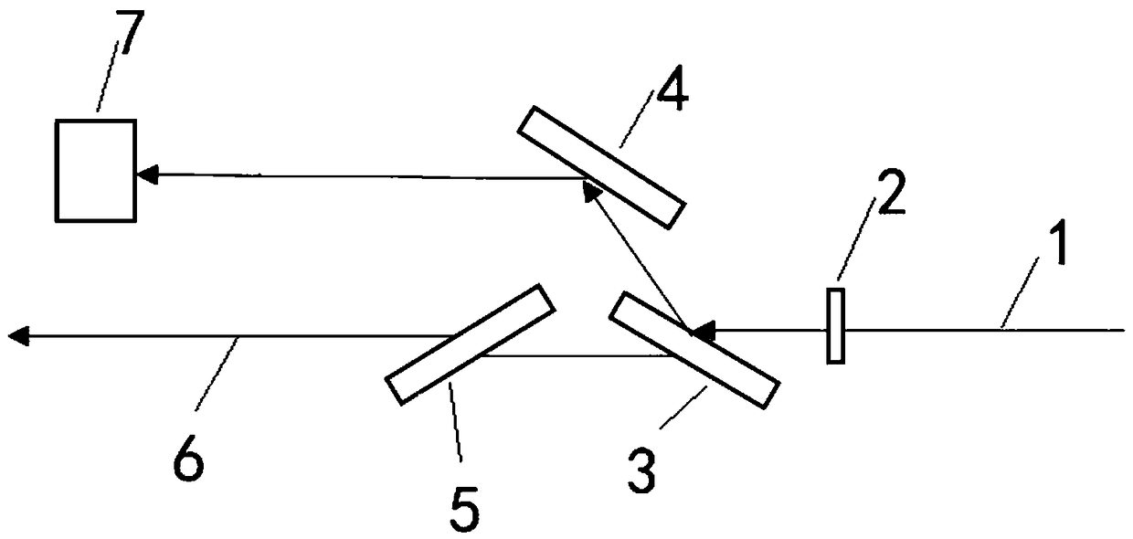
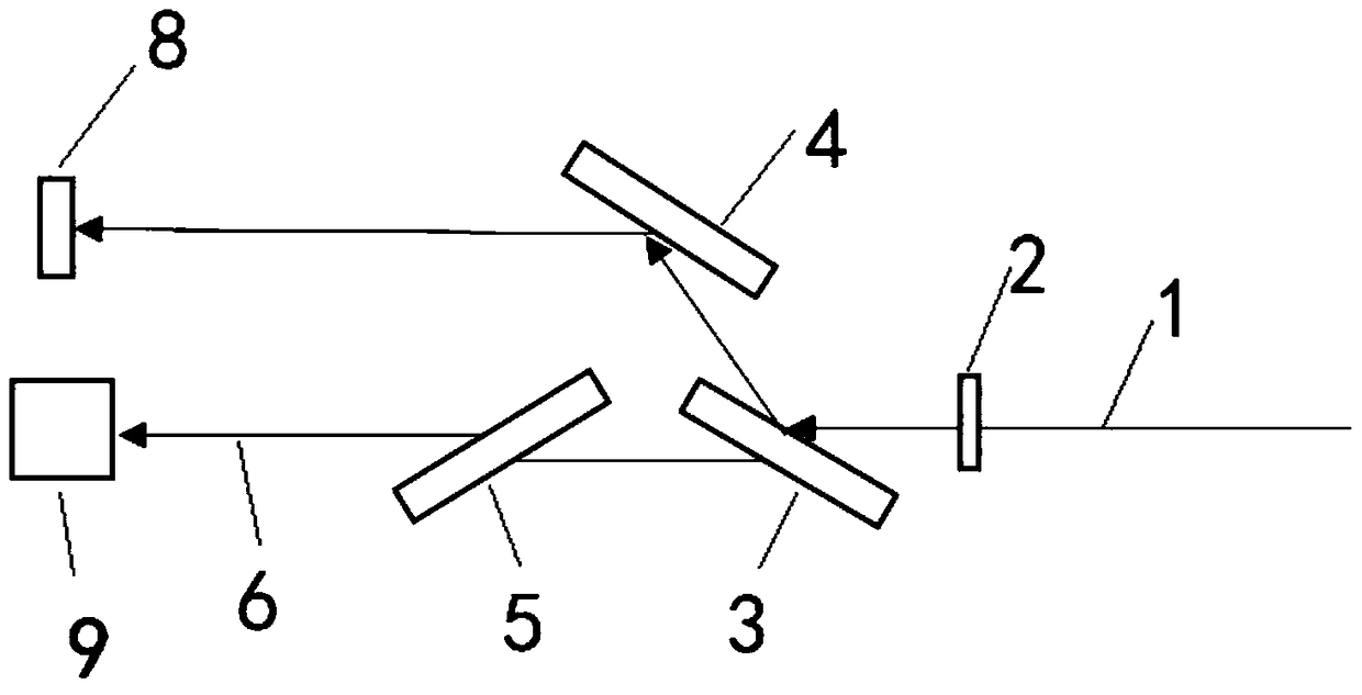
[0064] A measuring device for a measuring method of a laser beam quality factor M2, the measuring device for a measuring method for a laser beam quality factor M2 includes an optical path component, a measuring component, and an attenuation component;

[0065] see figure 2 , the optical path assembly includes a half-wave plate 2 and a first polarizer 3 arranged in sequence along the optical axis of the incident light beam 1, the first polarizer 3 is arranged to be inclined from left to right, and the reflection of the first polarizer 3 A second polarizer 4 is arranged on the optical axis of the light beam, and the second polarizer 4 is arranged to be inclined from left to right. The second polarizer 4 is located above the first polarizer 3. The incident beam 1, the first polarizer The reflected beam of 3 and the reflected beam of the second polarizer 4 form a "Z" shape structure, and the incident beam 1 and the reflected beam of the second polarizer 4 are parallel; the optica...


PUM


Abstract

The invention, which belongs to the technical field of lasers, discloses a measuring method of a laser beam quality factor M2 and a measuring device thereof. According to the measuring method, primarylight spot diameter measurement is carried out; to be specific, a CCD moves back and forth after a positive lens L1 to search for and measure a girdling diameter d1 of a smallest light spot; secondary light spot diameter measurement is carried out; to be specific, a light spot diameter d2 is measured at a focal plane position after a focusing lens L2, a divergence angle is obtained by a formula (1) and then a laser beam quality factor M2 is obtained by a formula (2). According to the method of two-times focusing with two lenses, the laser beam quality factor M2 is obtained only by measuring the light spot diameters twice; and compared with the prior art of curve fitting, the measuring method disclosed by the invention is implemented simply and conveniently.

Description

technical field [0001] The invention belongs to the technical field of lasers, and in particular relates to a method for measuring the quality factor M2 of a laser beam and a measuring device thereof. Background technique [0002] In 1988, A.E.Siegman used the dimensionless quantity—the beam quality factor M2 to describe the quality of the laser beam more scientifically and reasonably, and it was adopted by the International Standards Organization (ISO). M2 overcomes the limitations of commonly used beam quality evaluation methods, and is of great significance to the evaluation of laser beams. [0003] The concept of laser beam quality factor M2: The M2 factor is called the laser beam quality factor or diffraction-limited factor, which is defined as: the product of the actual beam waist width and the far-field beam divergence angle ratio of the beam waist width of the fundamental mode Gaussian beam and The product of the far-field beam divergence angles. [0004] For the f...

Claims


Application Information

Patent Timeline
Patent Type & Authority Applications(China)
IPC IPC(8): G01M11/02G01J1/00
CPCG01J1/00G01M11/02
Inventor 石朝辉王培峰王儒琦
Owner 索镭德激光科技(苏州)有限公司
Learn More