Light reception sub-module and optical module

An optical receiving sub-module and optical receiving technology, applied in the field of optical communication, can solve problems such as poor electrical isolation of the optical receiving sub-module, achieve good electrical isolation, and improve signal transmission quality

Inactive Publication Date: 2019-01-01
HISENSE BROADBAND MULTIMEDIA TECH
View PDF5 Cites 5 Cited by
  • Summary
  • Abstract
  • Description
  • Claims
  • Application Information

AI Technical Summary

Problems solved by technology

[0004] The invention provides an optical receiving sub-module and an optical module to solve the problem of poor electrical isolation effect of the existing optical receiving sub-module

Method used


Image

  • Light reception sub-module and optical module
  • Light reception sub-module and optical module
  • Light reception sub-module and optical module

Examples


Embodiment Construction

[0031] In the prior art, in order to realize high-speed signal transmission, the light-receiving sub-module usually puts a light-receiving driver chip such as a TIA into a packaging case, but this change needs to provide a suitable electrical isolation solution for the light-receiving driver chip. However, the current electrical isolation scheme of the optical receiving driver chip has the problem of poor electrical isolation effect, which leads to poor electrical isolation effect of the optical receiving sub-module.

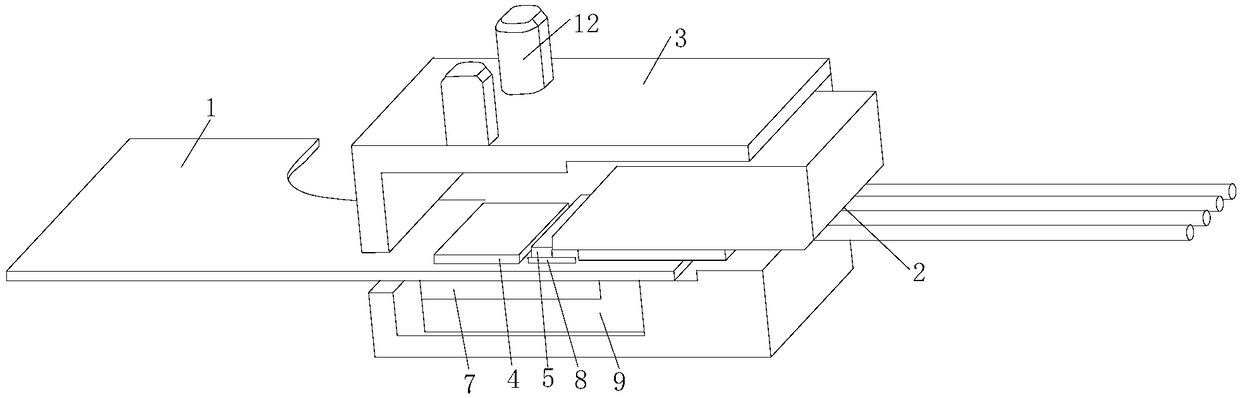
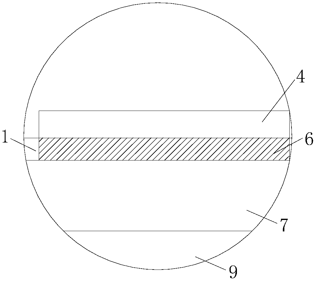
[0032] In view of the above problems, the present application provides an optical receiving sub-module and an optical module to solve the problem of poor electrical isolation effect of the optical receiving sub-module. The core idea of ​​the optical receiving sub-module and the optical module provided in this application is that the optical receiving sub-module includes a metal casing, and the flexible board and the light transmission array extend into the metal ...


PUM


Abstract

The invention provides a light reception sub-module and an optical module. The light reception sub-module comprises a metal casing, and a flexible board and a light transmission array extend into themetal casing. The flexible board is provided with a metal layer, and the upper and lower surfaces of the flexible board are provided with a light reception driving chip and a metal cushion block respectively. The metal layer makes contact with the light reception driving chip and the metal cushion block. The surface of the metal cushion block is provided with a metal boss, and a light reception chip is arranged on the metal boss. The light reception chip is in wiring connection with the light reception driving chip. The tail end of the light transmission array includes a reflection inclined plane, and used to transmit light to the light reception chip. An insulated heat-conduction cushion block is arranged between the bottom of the metal casing and the metal cushion block, and used to isolate the metal casing from the metal cushion block. Thus, electric transmission does not occur between the metal casing and the metal cushion block or between the flexible board and the metal casing, the light reception sub-module has a good electric isolation effect, and further the optical module has a good electric isolation effect.

Description

technical field [0001] The invention relates to the technical field of optical communication, in particular to an optical receiving sub-module and an optical module. Background technique [0002] The optical module is an important device for realizing photoelectric conversion in the optical fiber communication system, and it mainly includes a Transmitter Optical Subassembly (TOSA) and a Receiver Optical Subassembly (ROSA). Usually, the optical transmitting sub-module converts electrical signals into optical signals through lasers, and the optical signals are transmitted through optical fibers; the optical receiving sub-module receives optical signals transmitted by optical fibers, and converts optical signals into electrical signals, thereby realizing the photoelectricity of the optical module conversion function. [0003] In the prior art, in order to realize the transmission of high-speed signals, the optical receiving sub-module usually puts optical receiving driver chip...

Claims


Application Information

Patent Timeline
Patent Type & Authority Applications(China)
IPC IPC(8): G02B6/42
CPCG02B6/4214G02B6/4256G02B6/4268G02B6/4279G02B6/4281G02B6/4283
Inventor 刘鹏飞刘维伟傅钦豪
Owner HISENSE BROADBAND MULTIMEDIA TECH
Why Eureka
Try Eureka