

A temperature-controlled safe catalytic oxidation vocs treatment method
A catalytic oxidation and safe technology, applied in chemical instruments and methods, separation methods, gas treatment, etc., can solve the problems of insufficient heat storage capacity, potential safety hazards, and explosion hazards of heat storage ceramics, and achieve accurate and reliable temperature of heat transfer materials. control, energy-saving effect, and system safety and reliability
- Summary
- Abstract
- Description
- Claims
- Application Information
AI Technical Summary
Problems solved by technology
Method used
Image

Examples
Embodiment 1
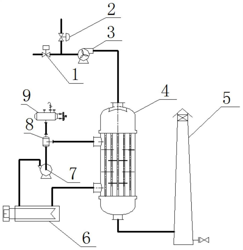
[0040] Such as figure 1The temperature-controlled safe catalytic oxidation VOCs treatment device shown includes a catalytic reactor 4 and an air intake system connected to the catalytic reactor 4, a heat transfer oil circulation system and an air outlet system. The catalytic reactor 4 is provided with a reactor tube 43 , the upper layer of the reactor tube 43 is filled with stainless steel wire mesh or ceramic balls 431, the middle layer is filled with a catalyst 432, and the lower layer is filled with heat-conducting and supporting ceramic balls 433; between the reactor tube 43 and the catalytic reactor 4 The sealed cavity between them is filled with heat-conducting oil; the heat-conducting oil circulation system includes an oil-gas separator 8, a heat-conducting oil pump 7 and an electric heater 6 connected in sequence, and the oil-gas separator 8 is connected to the heat-conducting oil outlet 46 of the catalytic reactor 4 through a pipeline , the electric heater 6 is connec...
Embodiment 2
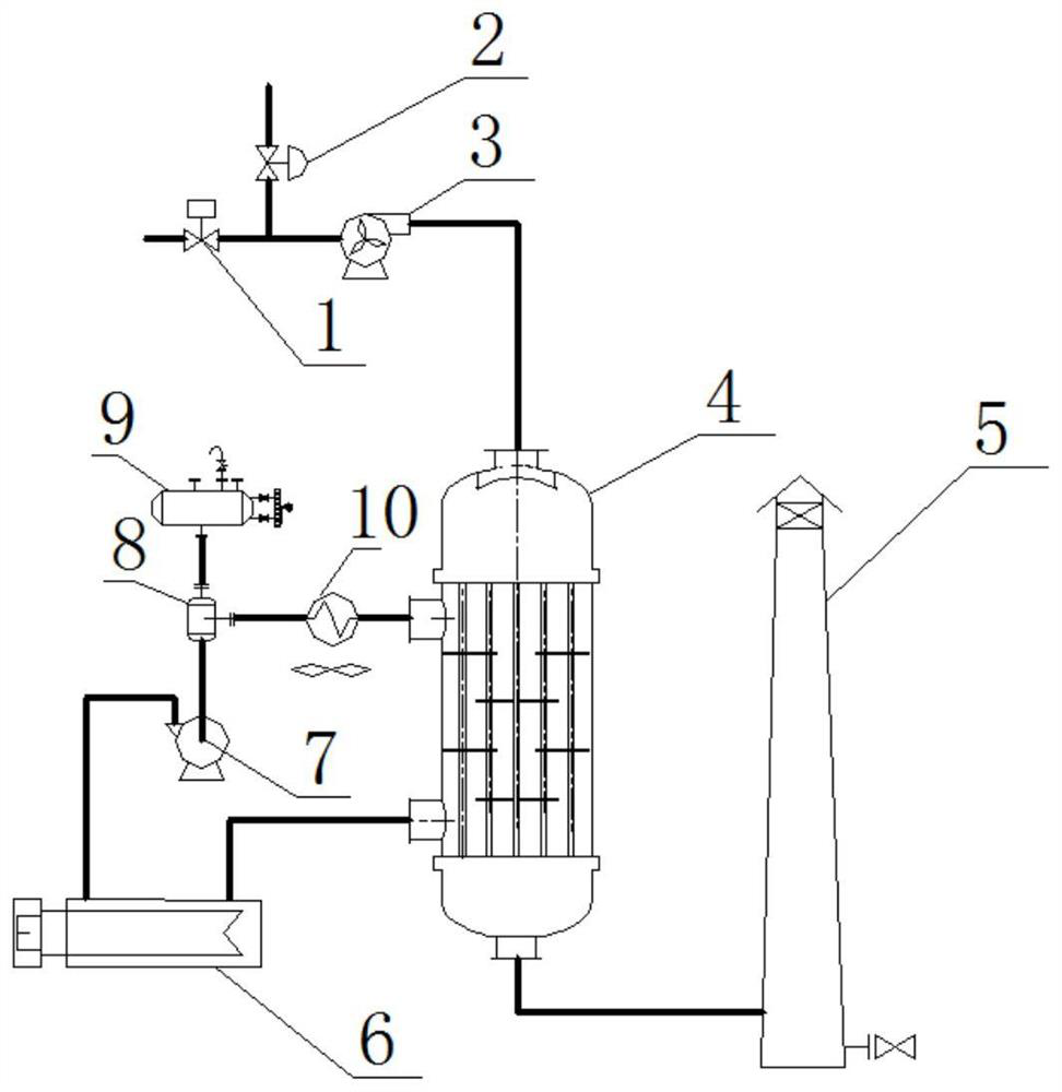
[0048] Such as figure 2 As shown, on the basis of Embodiment 1, a condensing unit 10 is added to the thermal circulation system of heat transfer oil, which is composed of a condenser and a cooling fan. The "high temperature" heat transfer oil can be cooled down through the condenser and cooling fan, which can better control the temperature of the heat transfer oil, so as not to cause "flying temperature" phenomenon, and can quickly take away the excessive heat released in the catalytic reactor 4.
Embodiment 3
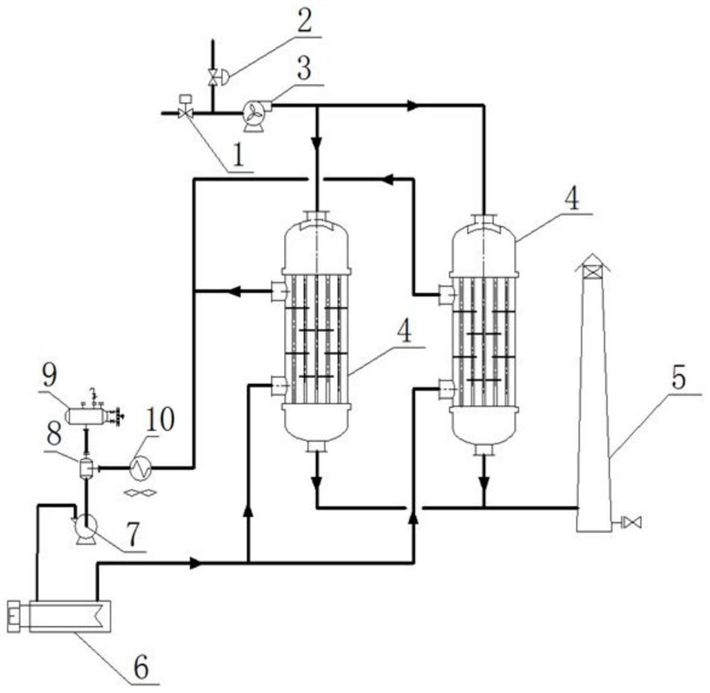
[0050] Such as image 3 As shown, the catalytic reactor 4 includes two in parallel, and the mixed and diluted gas is transported to the two catalytic reactors 4 respectively through the blower, and the mixed gas exchanges heat with the heat transfer oil medium in the catalytic reactor 4 and raises the temperature to reach the initial stage of the reaction. temperature, and converted into carbon dioxide and water vapor under the action of the catalyst 432 in the middle layer of the reactor tube 43, releasing heat, which is then exchanged with the heat transfer oil in the lower layer of the reactor to lower the temperature. The two catalytic reactors 4 are identical in structure. The gas treatment capacity after the two catalytic reactors 4 are used in parallel is much larger than the processing scale of a single catalytic reactor 4 . The heat storage systems of the two catalytic reactors 4 are composed of a heat transfer oil circulation system.
PUM
 Abstract
Description
Claims
Application Information