Device and process for continuously producing chloroacetic acid by differential circle flow
A chloroacetic acid, differential technology, applied in chlorine/hydrogen chloride, carboxylic acid anhydride preparation, halogen/halogen acid and other directions, can solve the problems of large investment, environmental pollution, high production cost, save the absorption device, "reduce escape, production Efficient effect
- Summary
- Abstract
- Description
- Claims
- Application Information
AI Technical Summary
Problems solved by technology
Method used
Image

Examples
Embodiment 1
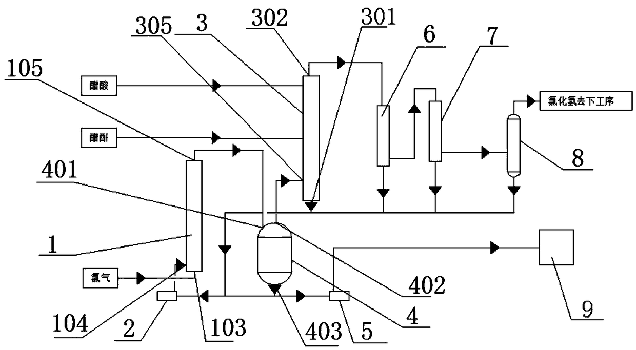
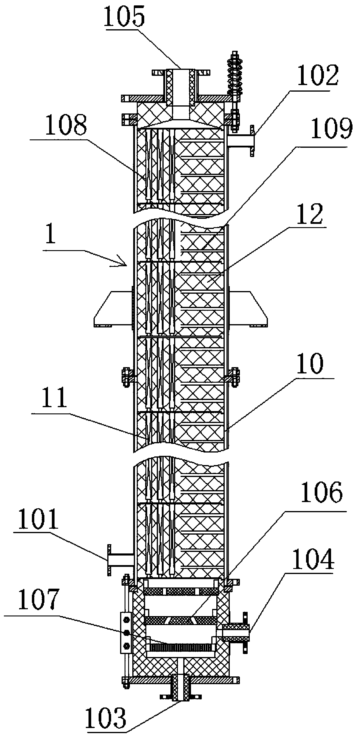
[0052] Step 1: The chlorinated liquid in the separator 4 is discharged from the separator liquid outlet 403 and pressurized by the circulation pump 2 and enters the gas-liquid mixing chamber 107 from the main reactor liquid inlet 104 at the bottom of the main reactor 1, and the chlorine gas is discharged from the main reactor The gas inlet 103 enters the gas-liquid mixing chamber 107. After mixing, it enters the main reactor tube side 108 for chemical reaction. The reaction temperature is 80°C and the reaction pressure is 80KPa. The reacted mixed liquid passes through the main reactor outlet 105 and the separator After the mixed liquid inlet 401, it flows back to the separator 4 for gas-liquid separation;
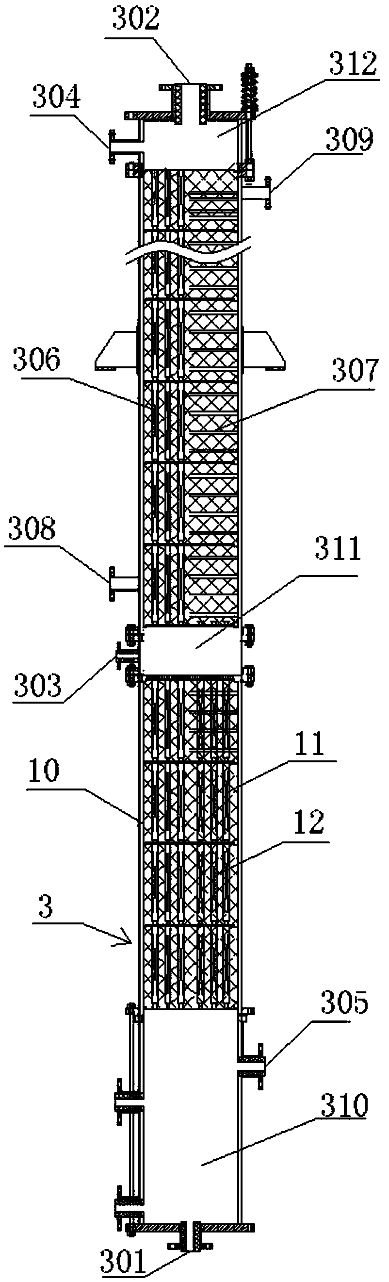
[0053] Step 2: After the separated hydrogen chloride gas is discharged from the separator gas outlet 402, it enters the prereactor mixing chamber 310 through the prereactor gas inlet 305, and the chlorinated liquid in the separator 4 enters the main reactor 1 again through t...
Embodiment 2
[0061] Step 1: The chlorinated liquid in the separator 4 is discharged from the separator liquid outlet 403 and pressurized by the circulation pump 2 and enters the gas-liquid mixing chamber 107 from the main reactor liquid inlet 104 at the bottom of the main reactor 1, and the chlorine gas is discharged from the main reactor The gas inlet 103 enters the gas-liquid mixing chamber 107. After mixing, it enters the main reactor tube side 108 for chemical reaction. The reaction temperature is 105°C and the reaction pressure is 250KPa. The reacted mixed liquid passes through the main reactor outlet 105 and the separator After the mixed liquid inlet 401, it flows back to the separator 4 for gas-liquid separation;
[0062] Step 2: After the separated hydrogen chloride gas is discharged from the separator gas outlet 402, it enters the prereactor mixing chamber 310 through the prereactor gas inlet 305, and the chlorinated liquid in the separator 4 enters the main reactor 1 again through...
Embodiment 3
[0070] Step 1: The chlorinated liquid in the separator 4 is discharged from the separator liquid outlet 403 and pressurized by the circulation pump 2 and enters the gas-liquid mixing chamber 107 from the main reactor liquid inlet 104 at the bottom of the main reactor 1, and the chlorine gas is discharged from the main reactor The gas inlet 103 enters the gas-liquid mixing chamber 107. After mixing, it enters the main reactor tube side 108 for chemical reaction. The reaction temperature is 90°C and the reaction pressure is 170KPa. The reacted mixed liquid passes through the main reactor outlet 105 and the separator After the mixed liquid inlet 401, it flows back to the separator 4 for gas-liquid separation;
[0071] Step 2: After the separated hydrogen chloride gas is discharged from the separator gas outlet 402, it enters the prereactor mixing chamber 310 through the prereactor gas inlet 305, and the chlorinated liquid in the separator 4 enters the main reactor 1 again through ...
PUM
 Abstract
Description
Claims
Application Information
 - R&D
- Intellectual Property
- Life Sciences
- Materials
- Tech Scout
- Unparalleled Data Quality
- Higher Quality Content
- 60% Fewer Hallucinations
Browse by: Latest US Patents, China's latest patents, Technical Efficacy Thesaurus, Application Domain, Technology Topic, Popular Technical Reports.
© 2025 PatSnap. All rights reserved.Legal|Privacy policy|Modern Slavery Act Transparency Statement|Sitemap|About US| Contact US: help@patsnap.com